Combined device for bending and cutting ribbon-shaped elements and method for bending and cutting ribbon-shaped elements through such device

Active Publication Date: 2019-06-25
BYTE LINE DI PELISSERO ALESSANDRO
View PDF5 Cites 0 Cited by
  • Summary
  • Abstract
  • Description
  • Claims
  • Application Information

AI Technical Summary

Benefits of technology

[0017]Another object is providing a device with limited needs of recurring to guides, capable of making bends next to the end and of not needing dummy pieces.
[0018]A further object is providing a device which does not need to widen the bends in order

Problems solved by technology

In fact, the bent profile of the end of a ribbon could interfere with the device for the final cut.
Under the same other conditions, the second method in general is much more costly that the first one.
But

Method used


Image

  • Combined device for bending and cutting ribbon-shaped elements and method for bending and cutting ribbon-shaped elements through such device
  • Combined device for bending and cutting ribbon-shaped elements and method for bending and cutting ribbon-shaped elements through such device
  • Combined device for bending and cutting ribbon-shaped elements and method for bending and cutting ribbon-shaped elements through such device

Examples


Example

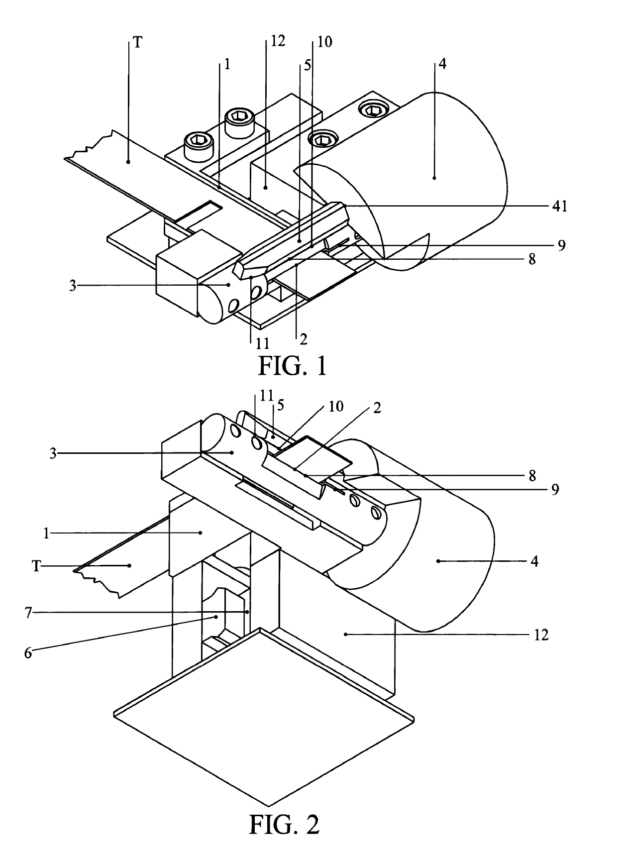
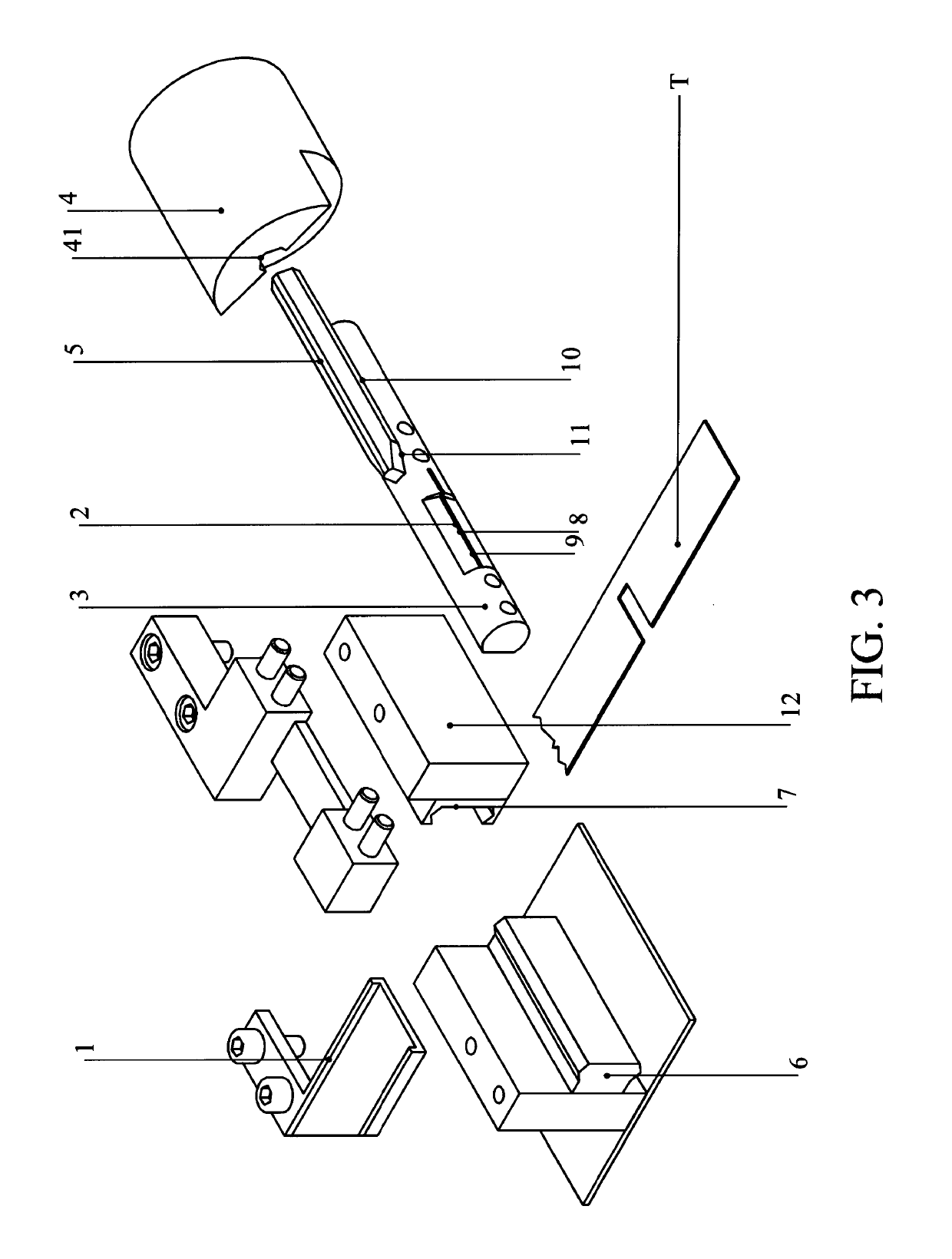
[0042]With reference to FIGS. 1 to 12, 20, 21, it is possible to note that a combined device for bending and cutting ribbon-shaped elements comprises: first guiding and supporting means 1, 101 adapted to allow positioning at least one ribbon-shaped element T, T1; second guiding and supporting means 3, 103 adapted to prevent the rotation of the ribbon-shaped element T, T1 with respect to an axis belonging to the plane on which the ribbon-shaped element T, T1 rests; first translating means 41, 1041 and rotation means 4, 104 adapted to move at least one tool 5, 105 with respect to the second guiding and supporting means 3, 103.

[0043]Such second guiding and supporting means 3, 103 comprise at least one portion of bending profile 8, 108 adapted to bend the ribbon-shaped element T, T1 and at least one portion of cutting profile 9, 109 adapted to cut the ribbon-shaped element T, T1.

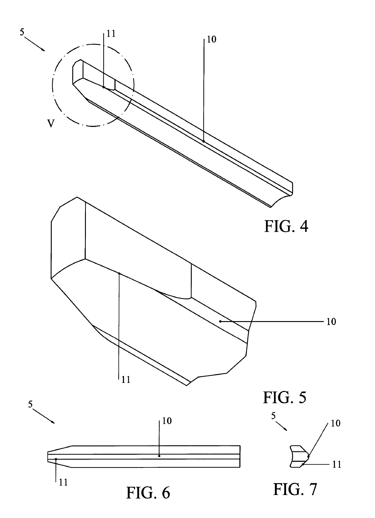
[0044]The first translating means 41, 1041 allow aligning at least one portion of bending profile 10, 110 of ...


PUM


Abstract

A combined device for bending and cutting ribbon-shaped elements is described, comprising first guiding and supporting means (1, 101) adapted to allow positioning a ribbon-shaped element (T, T1), second guiding and supporting means (3, 103) adapted to prevent the rotation of the ribbon-shaped element (T, T1) with respect to an axis belonging to a plane on which the ribbon-shaped element (T, T1) rests, first translating means (41, 1041) and rotation means (4, 104) adapted to move a tool (5, 105) with respect to the second guiding and supporting means (3, 103); the second guiding and supporting means (3, 103) comprise a portion of bending profile (8, 108) adapted to bend the ribbon-shaped element (T, T1) and a portion of cutting profile (9, 109) adapted to cut the ribbon-shaped element (T, T1). A method is further described for bending and cutting ribbon-shaped elements performed through such device.

Description


Claims


Application Information

Patent Timeline
Owner BYTE LINE DI PELISSERO ALESSANDRO
Why Eureka
Try Eureka