Behind-the-ear hearing aid with integrally-molded instrument case

Inactive Publication Date: 2007-08-23
LE ANTHONY D
6 Cites 16 Cited by

AI-Extracted Technical Summary

Problems solved by technology

Unfortunately, today 1 in 10 Americans (over 30 million people) experience some degree of hearing loss.
Additionally, the problem of hearing loss is “growing younger.” 15% of recent college graduates have as much or more hearing loss than their parents.
DSP hearing aids (like most others) are quite expensive, typically costing several thousands of dollars.
Some hearing aids are well sealed, while others require more care and are more prone to damage—particularly, BTE hearing aids.
There is no standard manufacturing p...

Benefits of technology

[0011] It is another object of the invention to provide a BTE hearing aid which limits the need for drying kits which could be harmful to Zinc-air batteries.
[0012] It is another object of the invention to provide a BTE hearing aid whic...

Abstract

A behind-the-ear hearing aid including an arcuate, integrally-molded instrument case adapted for residing behind an ear of a wearer. The instrument case defines a substantially seamless electronics compartment containing a microphone and a loudspeaker operatively connected to the microphone. An amplifier serves to boost a sound signal transmitted from the microphone through the loudspeaker to the ear of the wearer.

Application Domain

Behind the ear hearing aidsHearing aids housing +1

Technology Topic

Image

  • Behind-the-ear hearing aid with integrally-molded instrument case
  • Behind-the-ear hearing aid with integrally-molded instrument case
  • Behind-the-ear hearing aid with integrally-molded instrument case

Examples

  • Experimental program(1)

Example

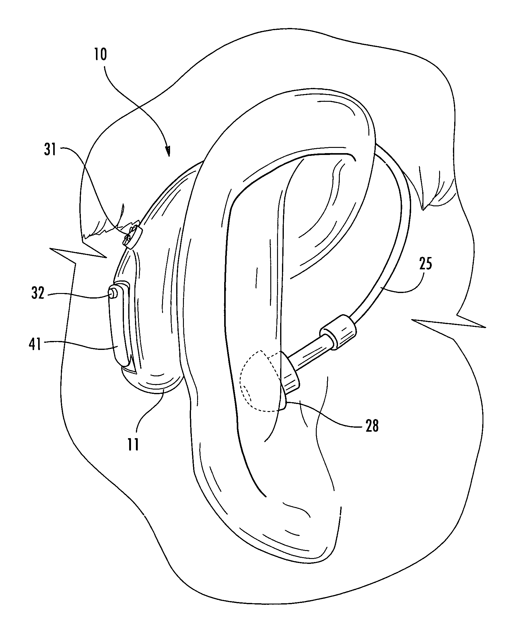
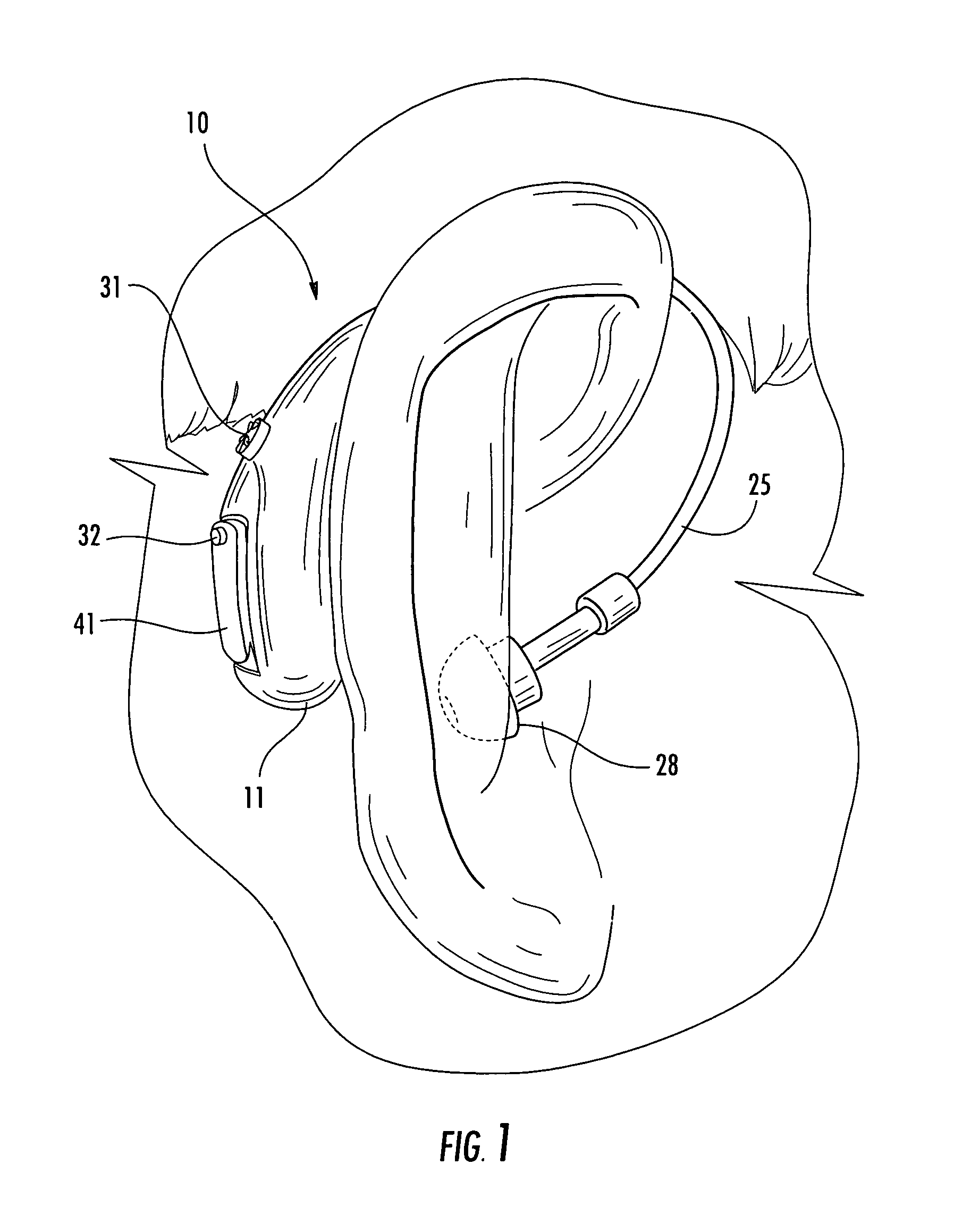
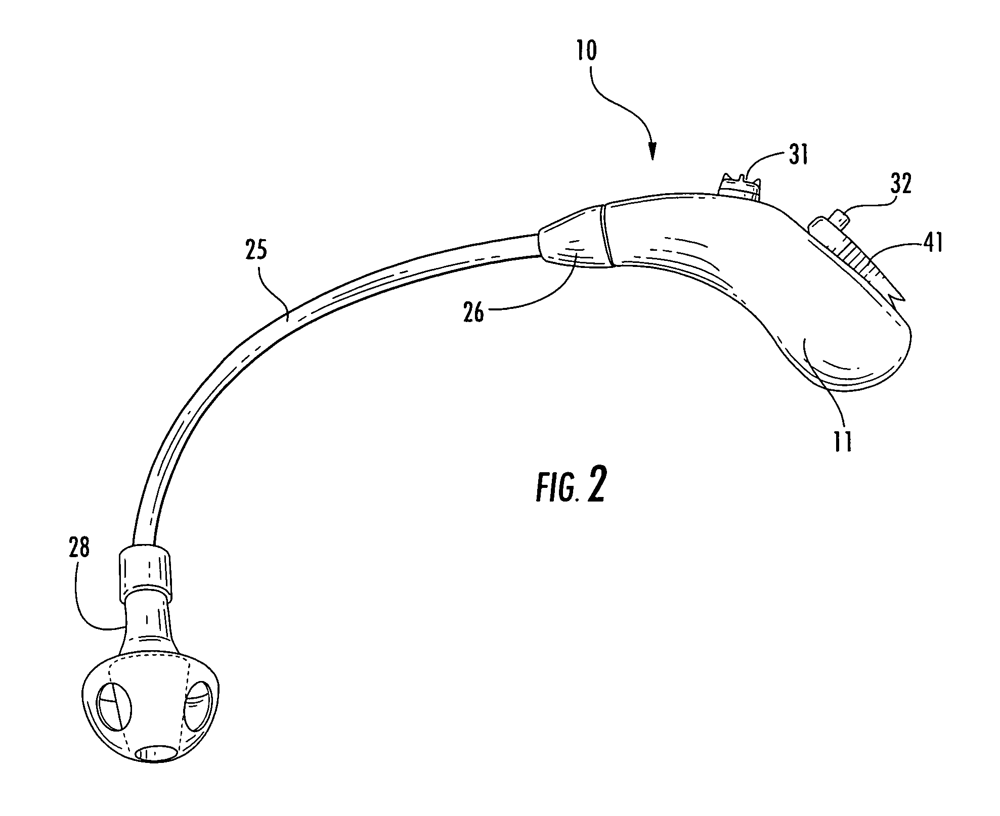
[0035] Referring now specifically to the drawings, a BTE hearing aid according to the present invention is illustrated in FIGS. 1 and 2, and shown generally at reference numeral 10. The hearing aid 10 comprises a sleek, ergonomic, integrally-molded instrument case 11 which is designed to reside behind an ear of the wearer.
[0036] As best shown in FIGS. 3 and 4, the instrument case 11 forms a substantially seamless electronics compartment 12. Conventional components including a microphone 14, loudspeaker 15, computer chip 16 and battery 17 are all housed in the electronics compartment 12. By inserting a programming strip (not shown) through slot 21 in the instrument case 11, the computer chip 16 is programmed to match a particular hearing loss with the most prescriptive amplification needed. The programming strip contacts a flex PCB interface 22.
[0037] Using known DSP technology, the hearing aid 10 converts a sound signal received at the microphone 14 into a digital format before processing it, and then converts it back to analog before sending the signal to the loudspeaker 15. From the loudspeaker 15, the sound signal exits the instrument case 11 through sound port 24, and is transmitted through a flexible sound tube 25 to the ear of the wearer. The sound tube 25 has an internally-threaded fitting 26 at its proximal end which mates with a complementary-threaded connector 27 attached to the instrument case 11. A replaceable and exchangeable ear tip 28 is located at the free end of the sound tube 25.
[0038] Preferably, the hearing aid 10 further includes a standard volume control wheel 31 and memory button 32. The volume control wheel 31 enables convenient manual adjustment of tone (low and high frequencies) and volume so that the wearer can hear enhanced sounds within a comfortable tolerance level. The memory button 32 allows the wearer to change between various pre-programmed listening programs.
[0039] The instrument case 11 is preferably manufactured in a single-cavity mold. Generally described, the mold is first heated in water, and air blown through it to clear away any impurities. A technician then mixes liquid acrylic of equal parts monomer and polymer, and adds the desired pigment to give the case a pink, tan, or brown color. The technician pours the liquid into the heated mold, and then pours off any excess, leaving a thin acrylic shell inside the mold. The resulting instrument case 11 has a small microphone port 33 and an access opening 34 (FIG. 3) to the electronics compartment 12.
[0040] Referring to FIGS. 3, 4, and 6, a detachable mounting frame 35 is located at a mouth of the access opening 34, and serves to carry (in a single module) various internal components of the hearing aid including the microphone 14, computer chip 16, and opposing battery springs 38 and 39. This convenient modular assembly of hardware allows the case 11 to be manufactured as a small integrally-formed unit without employing a standard face plate for mounting the hardware. The present construction thereby facilitates access to internal parts, and assembly and replacement of parts. The mounting frame 35 is preferably held in place at the access opening 34 using a light contact adhesive or other suitable means.
[0041] According to one embodiment, the mounting frame 35 is manufactured using stereolithography and selective laser sintering systems known in the art. The access opening 34 is selectively opened and closed via a pivoted access door 41. The access door 41 has an arcuate battery arm 42, best shown in FIGS. 3, 5, and 6, designed for holding the battery 17 such that when the door 41 is closed, the battery 17 engages the springs 38, 39 at respective positive and negative contacts. Preferably, the battery 17 is a small Zinc-air battery commonly used in other prior art hearing aids.
[0042] Because of its substantially seamless design, the instrument case 11 limits entry of harmful moisture and/or foreign matter into the electronics compartment 12. The total seam length across the instrument case 11 at the access opening 34 and mounting frame 35, and around a circular opening 44 for the volume control wheel 31 is preferably less than 50 mm, and more preferably less than 40 mm, and most preferably between 25-40 mm.
[0043] A BTE hearing aid is described above. Various details of the invention may be changed without departing from its scope. Furthermore, the foregoing description of the preferred embodiment of the invention and best mode for practicing the invention are provided for the purpose of illustration only and not for the purpose of limitation—the invention being defined by the claims.

PUM

no PUM

Description & Claims & Application Information

We can also present the details of the Description, Claims and Application information to help users get a comprehensive understanding of the technical details of the patent, such as background art, summary of invention, brief description of drawings, description of embodiments, and other original content. On the other hand, users can also determine the specific scope of protection of the technology through the list of claims; as well as understand the changes in the life cycle of the technology with the presentation of the patent timeline. Login to view more.

Similar technology patents

Capacity management and timing

InactiveUS20060106716A1Minimize or remove human interventionNeed be limitFinancePayment architecturePaymentComputer science
Owner:TALARIS HLDG

Media storage and management system

InactiveUS20140300983A1Quickly and efficiently manageNeed be limitRecord information storageDigital recordingData storage systemManagement system
Owner:ORACLE INT CORP

Pet cage

Owner:YANG WEIPING

Classification and recommendation of technical efficacy words

  • Need be limit
  • Convenient access

Pet waste collection apparatus

InactiveUS7096823B1Convenient accessReadily disposeAnimal housingOther apparatusFlangeFeces
Owner:SMELTZER MICHAEL

Password management

ActiveUS20050005132A1Convenient accessDigital data processing detailsMultiple digital computer combinationsResource useWindows Registry
Owner:IBM CORP

System and method for accessing through wireless internet access points information or services related to broadcast programs

InactiveUS20060136549A1Easily accessConvenient accessBroadcast services for monitoring/identification/recognitionMultiple digital computer combinationsRadio programHyperlink
Owner:LENOVO (SINGAPORE) PTE LTD
Why Eureka
Try Eureka