Walking assist device

a technology of assist device and walking aid, which is applied in the field of walking assist device, can solve the problems of inability to produce the optimal assist force, difficulty in estimating the phase of motion of the lower limb, and inability to accurately estimate the phase of motion of the user's lower limbs

Active Publication Date: 2019-07-16
HONDA MOTOR CO LTD
View PDF6 Cites 6 Cited by
  • Summary
  • Abstract
  • Description
  • Claims
  • Application Information

AI Technical Summary

Benefits of technology

[0025]Thus, the present invention provides a walking assist device that can provide an appropriate cyclic assistance to a user without requiring any complex parameter setting even when the user suffers from an asymmetric disability.

Problems solved by technology

When a user who is incapable of a symmetric walking motion, in terms of space and / or time, owing to the disablement of one of the lower limbs wears the walking assist device, the motion of the disabled lower limb involves a smaller stroke and lacks in cyclic tendencies so that some difficulty often arises in estimating the phase of the motion of the lower limbs.
When an assist force (torque) based on an inaccurate estimation of the phase of the motion of the lower limbs is applied to the user, the assist force may not completely match the motion of the lower limbs of the user so that the gait of the user may even be destabilized.
Therefore, when such a motion assist device is applied to a user with an asymmetric disability, the phase of the motion of the disabled body lower limb cannot be correctly determined so that an optimum assist force cannot be produced.

Method used


Image

  • Walking assist device
  • Walking assist device
  • Walking assist device

Examples


first embodiment

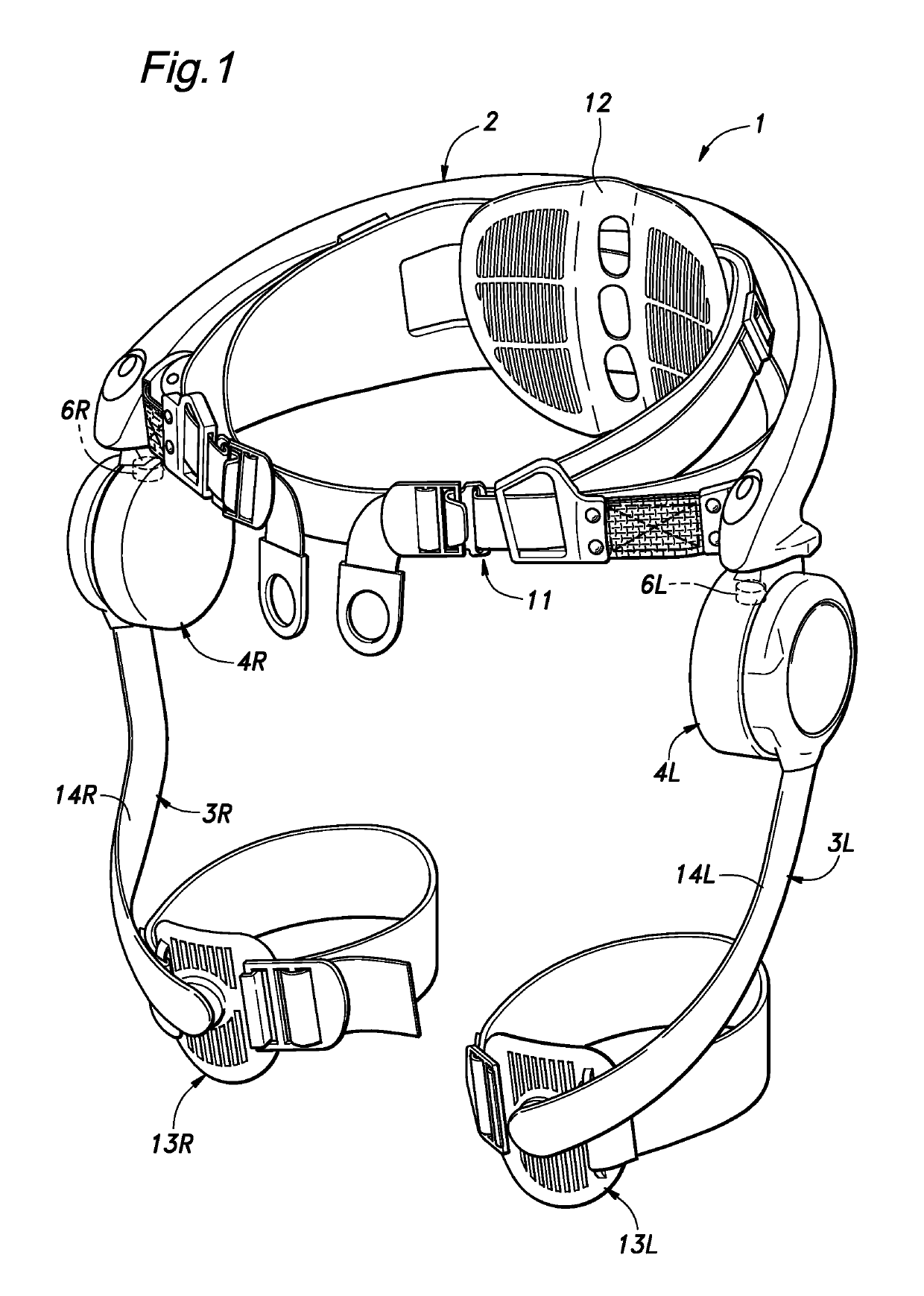
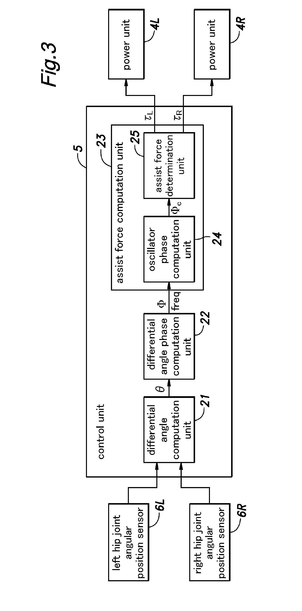
[0044]As shown in FIG. 1, the walking assist device 1 of the first embodiment includes a main frame 2 configured to be worn on a pelvic part of the user P, a pair of femoral support units 3 (3L and 3R) pivotally attached to either side part of the main frame 2 at the positions corresponding to the hip joints of the user P at the base ends thereof via respective power units 4, a control unit 5 (See FIG. 3) for controlling the operation of the power units 4, a pair of angular position sensors 6 for detecting the angles of the femoral support units 3 provided at the respective pivoted base ends of the femoral support units 3 with respect to the main frame 2 and a battery (not shown in the drawings) for supplying electric power to the power units 4 and the control unit 5.

[0045]The main frame 2 is made of a combination of stiff material such as hard plastics and metals and flexible material such as fabrics and foamed plastics, and is secured to the pelvic part of the user P by a belt 11 ...

second embodiment

[0101]A second embodiment of the present invention is described in the following with reference to FIG. 10.

[0102]FIG. 10 shows a modification of the differential angle computation unit 21 of the walking assist device 1 of the first embodiment shown in FIG. 3. The structure and the functions of the second embodiment are otherwise similar to those of the first embodiment. Therefore, the parts corresponding to those of the first embodiment are omitted, and only those parts that are different from the counterparts in the first embodiment are described in the following. The same is true with other embodiments that are described later.

[0103]In this embodiment, instead of using absolute type angular sensors for the hip joint angular position sensors 6L and 6R of the first embodiment, incremental type angular sensors 61L and 61R for detecting the angles of the femoral parts relative to the main frame 2 are used as shown in FIG. 10. The differential angle computation unit 21 computes the dif...

third embodiment

[0106]FIG. 11 shows the structure of the differential angle computation unit 21 in a third embodiment of the present invention.

[0107]In this embodiment, the walking assist device 1 is provided with a left femoral G sensor 71L and a right femoral G sensor 71R for detecting the fore and aft accelerations of the respective femoral support units 3L and 3R, and a left femoral gyro sensor 72L and a right femoral gyro sensor 72R for detecting the angular speeds ω3L and ω3R of the respective femoral support units 3L and 3R, instead of the hip joint angular position sensors 6L and 6R of the first embodiment. The differential angle computation unit 21 computes the differential angle θ from the output signals provided by these sensors 71L, 71R, 72L and 72R.

[0108]The differential angle computation unit 21 is provided with a left and right strap-down attitude estimation units 73L and 73R for estimating the respective attitude angle vectors BL and BR by executing a strap-down attitude estimation ...


PUM


Abstract

Provided is a walking assist device including a main frame configured to be worn by a user, a power unit mounted on the main frame, a pair of power transmission members for transmitting assist force provided by the power unit to femoral parts of the user and a control unit for controlling an operation of the power unit, wherein the control unit comprises a differential angle computation unit for computing a differential angle between angular positions of the femoral parts of the user about respective hip joints of the user; a differential angle phase computation unit for computing a differential angle phase according to the differential angle; and an assist force computation unit for computing an assist force to be applied to the user according to the differential angle phase.

Description

TECHNICAL FIELD[0001]The present invention relates to a walking assist device for assisting a walking movement of a user.BACKGROUND ART[0002]In recent years, various forms of motion assist devices configured to be worn by a user for medical and nursing purposes have been developed. As a control principle for such motion assist devices, a timing matching control for matching the timings of the user and the device is known. See Patent Document 1. According to the concept of the timing matching control, it is expected that the motion assist device is enabled to operate with a timing that favorably matches the timing of the walking movement of the user or is enabled to operate as a rehabilitation device with a motion teaching function by providing an assist force that teaches an optimum motion to the user before the user actually effects a corresponding motion. In the motion assist device of Patent Document 1, a mutually inhibiting model of a neural oscillator is used for generating a m...

Claims


Application Information

Patent Timeline
Patent Type & Authority Patents(United States)
IPC IPC(8): A61F3/00A61H3/00A61H1/02
CPCA61H3/00A61H1/0244A61H2003/007A61H2201/1215A61H2201/5058A61H2201/165A61H2201/1628A61H2201/5007A61H2201/164
Inventor TAKENAKA, TORUISHIKAWA, TATSUYAYASUHARA, KEN
Owner HONDA MOTOR CO LTD
Why Eureka
Try Eureka