
Zero G inertia exercise apparatus

a technology of exercise apparatus and zero g inertia, which is applied in the field of exercise apparatus and method, can solve the problems of ineffective exercise to maintain muscle mass in such an environment, and achieve the effect of stimulating bone development, eliminating and/or reducing bone mass loss

Active Publication Date: 2019-07-23
DAVISON STEVE W
View PDF19 Cites 0 Cited by
  • Summary
  • Abstract
  • Description
  • Claims
  • Application Information

AI Technical Summary

Benefits of technology

[0006]Impulse Training (“IT”) is a neuromuscular development tool that may be employed in micro-gravity and / or zero gravity environments to stimulate bone development and, therefore, to eliminate and / or reduce loss of bone mass when humans spend extended periods of time in microgravity or zero gravity environments.
[0017]Where a tether length adjustment mechanism is included, the tether length adjustment mechanism may include at least one tether collection tab, facilitating shortening of the tether, and at least one tether cinch tab, permitting securement of the tether in a shortened condition.

Problems solved by technology

While exercise can help to maintain muscle mass in a microgravity or zero gravity environment, exercise to maintain muscle mass in such an environment is ineffective in developing and / or maintaining bone mass in the same environment.

Method used


Image

  • Zero G inertia exercise apparatus
  • Zero G inertia exercise apparatus
  • Zero G inertia exercise apparatus

Examples


first embodiment

The The Rotary Platform

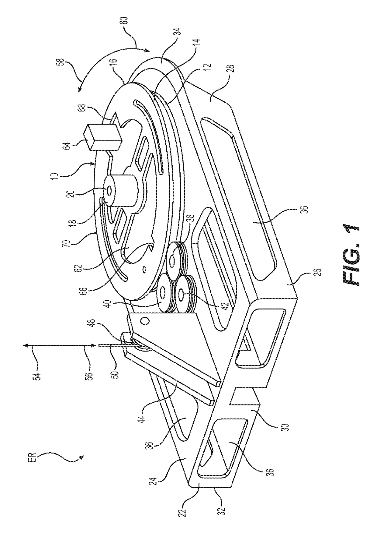
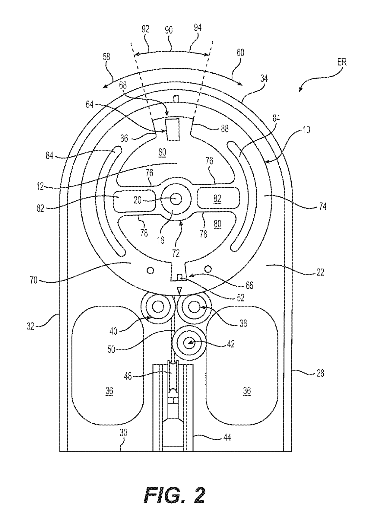
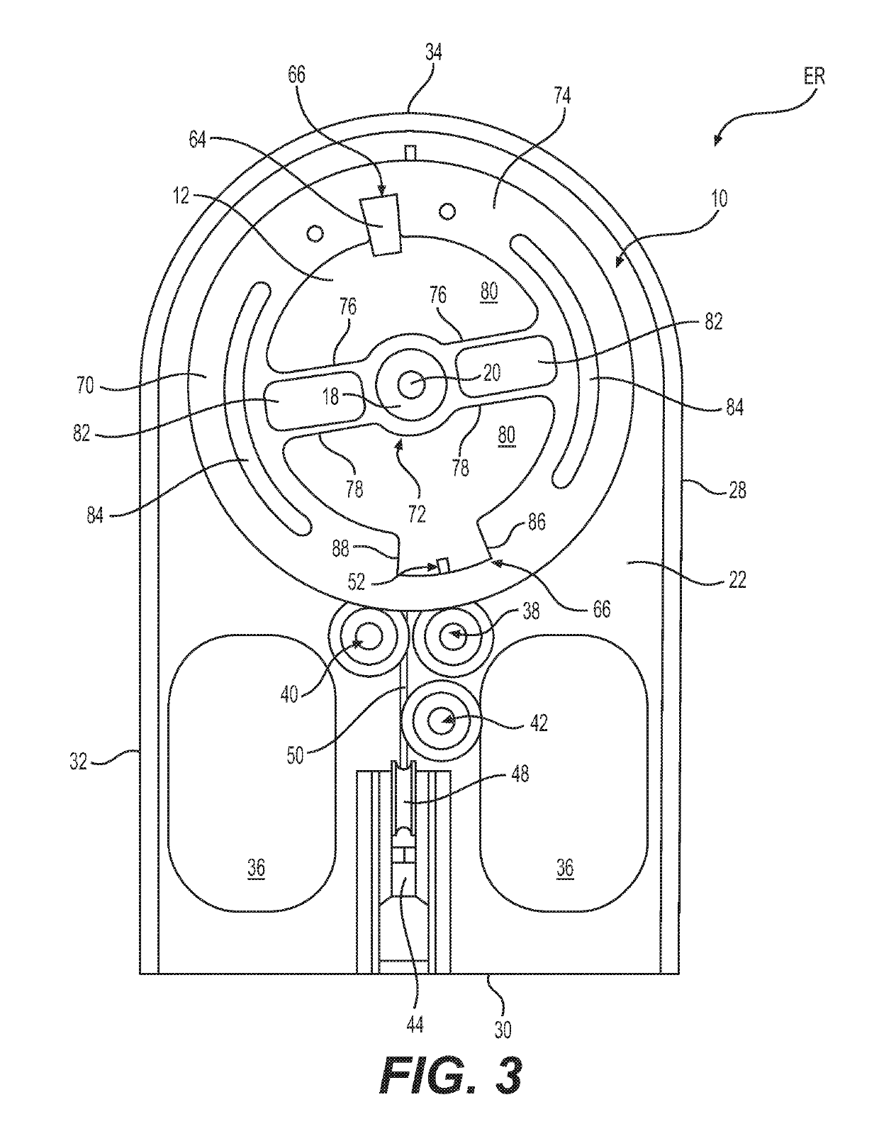
[0062]The first embodiment of a movable platform of the exerciser ER is illustrated in FIGS. 1-7.

[0063]In this first embodiment, the movable platform relies on rotary motion to generate the instantaneous force spikes. Accordingly, for this first embodiment, the movable platform is referred to as a rotary platform 10.

[0064]The rotary platform 10 encompasses a circular plate 12 with a peripheral groove 14 around its perimeter 16. The rotary platform 10 includes a hub 18 at its center. In the illustrated embodiment, the hub 18 is integrally formed with the circular plate 12. As such, the hub 18 is contemplated to rotate around a shaft 20 at the center of the hub 18. The shaft 20 is attached to a frame 22 that supports the rotary platform 10.

[0065]It is noted that the rotary platform 10 is not intended to be limited solely to the construction depicted. To the contrary, the rotary platform 10 may be constructed in any alternative manner as may be apparent to those...

second embodiment

The The Linear Platform

[0109]A second embodiment of the exerciser EL of the present invention is illustrated in FIGS. 8-15.

[0110]Aspects of elements of the exerciser ER apply equally to the exerciser EL. For example, the materials for various components apply to the equivalent components that form the exerciser EL

[0111]FIG. 8 is a perspective illustration of the exerciser EL, showing the overall construction for the exerciser EL.

[0112]According to the second embodiment of the present invention, the exerciser EL has a linear platform 110 that is slidably disposed on a frame 112. Here, the exerciser EL does not rely on rotary motion for acceleration, deceleration, and the generation of instantaneous force spikes, as discussed above in connection with the exerciser EL with the rotary platform 10.

[0113]As with the frame 22, the frame 112 may be made from any suitable material. Examples of suitable materials include, but are not limited to, lightweight materials, aluminum, aluminum allo...


PUM


Abstract

An exerciser includes a frame, a movable platform disposed on the frame, the movable platform being movable between a first position and a second position, at least one weight disposable on the moveable platform in a first orientation so that the at least one weight slides between a third position and a fourth position, and a tether connected to the moveable platform to move the moveable platform from the first position to the second position. The at least one weight slides to the third position when the movable platform reaches the first position. The at least one weight slides to the fourth position when the moveable platform reaches the second position.

Description

CROSS-REFERENCE TO RELATED. APPLICATION(S)[0001]This Non-Provisional U.S. Patent Application relies for priority on U.S. Provisional Patent Application 62 / 528,851, filed on Jul. 5, 2017, the entire contents of which are incorporated herein by reference.FIELD OF THE INVENTION[0002]The present invention concerns an exercise apparatus and method that, inter alia, stimulates bone growth and development.DESCRIPTION OF THE RELATED ART[0003]As should be apparent to those familiar with the effects of micro-gravity on human physiology, when humans spend extended time periods in space (i.e., in micro-gravity or zero gravity environments), humans lose both muscle and bone mass, because the body adjusts to the micro-gravity or zero gravity environment.[0004]While exercise can help to maintain muscle mass in a microgravity or zero gravity environment, exercise to maintain muscle mass in such an environment is ineffective in developing and / or maintaining bone mass in the same environment.[0005]As...

Claims


Application Information

Patent Timeline
Patent Type & Authority Patents(United States)
IPC IPC(8): A63B21/00A63B21/16A63B21/22A63B21/062
CPCA63B21/154A63B21/00061A63B21/22A63B21/16A63B21/062A63B21/00196A63B21/156A63B21/225A63B71/0036A63B2208/0204A63B2208/0257A63B2220/24A63B2220/51A63B21/0628A63B21/4035A63B21/4043A63B21/4045
Inventor DAVISON, STEVE W
Owner DAVISON STEVE W
Learn More