Supercharge Your Innovation With Domain-Expert AI Agents!

Buckle assembly

a technology of buckles and buckle latches, applied in the field of buckles, can solve the problems of insufficient engagement between the first buckle member and the second buckle member, the locking mechanism is far from reliable, and the buckle latch may be actuated, so as to achieve convenient operation and enhance the locking performan

Active Publication Date: 2019-08-13
HSU FRANK
View PDF2 Cites 2 Cited by
  • Summary
  • Abstract
  • Description
  • Claims
  • Application Information

AI Technical Summary

Benefits of technology

[0005]Certain variations of the present invention provide a buckle assembly which is capable of providing an enhanced locking performance and convenient operation.
[0006]Certain variations of the present invention provide a buckle assembly comprising a locking arrangement which is capable of minimizing lateral movements between a first buckle member and a second buckle member when they are engaged with each other.

Problems solved by technology

There are several disadvantages in relation to the above-mentioned buckle assembly.
First, the first buckle member and the second buckle member are usually locked by the buckle latches, and this locking mechanism is far from reliable.
One reason is that the buckle latches may be actuated by accident.
Second, even if the first buckle member and the second buckle member are engaged with each other in a proper manner, and the buckle latches are in their proper positions, the engagement between the first buckle member and the second buckle member may be not secure enough and there may exist a lot of relative movements between the first buckle member and the second buckle member.
Specifically, when the buckle assembly is being used in various activities, it may subject to a lot of impacts, movements, and vibrations.
When this relative movement becomes too large, the engagement between the insertion member and the buckle latches may become loose and the engagement between the first buckle member and the second buckle member may become substantially weaker.

Method used


Image

  • Buckle assembly
  • Buckle assembly
  • Buckle assembly

Examples


Embodiment Construction

[0023]The following detailed description of the preferred embodiment is the preferred mode of carrying out the invention. The description is not to be taken in any limiting sense. It is presented for the purpose of illustrating the general principles of the present invention.

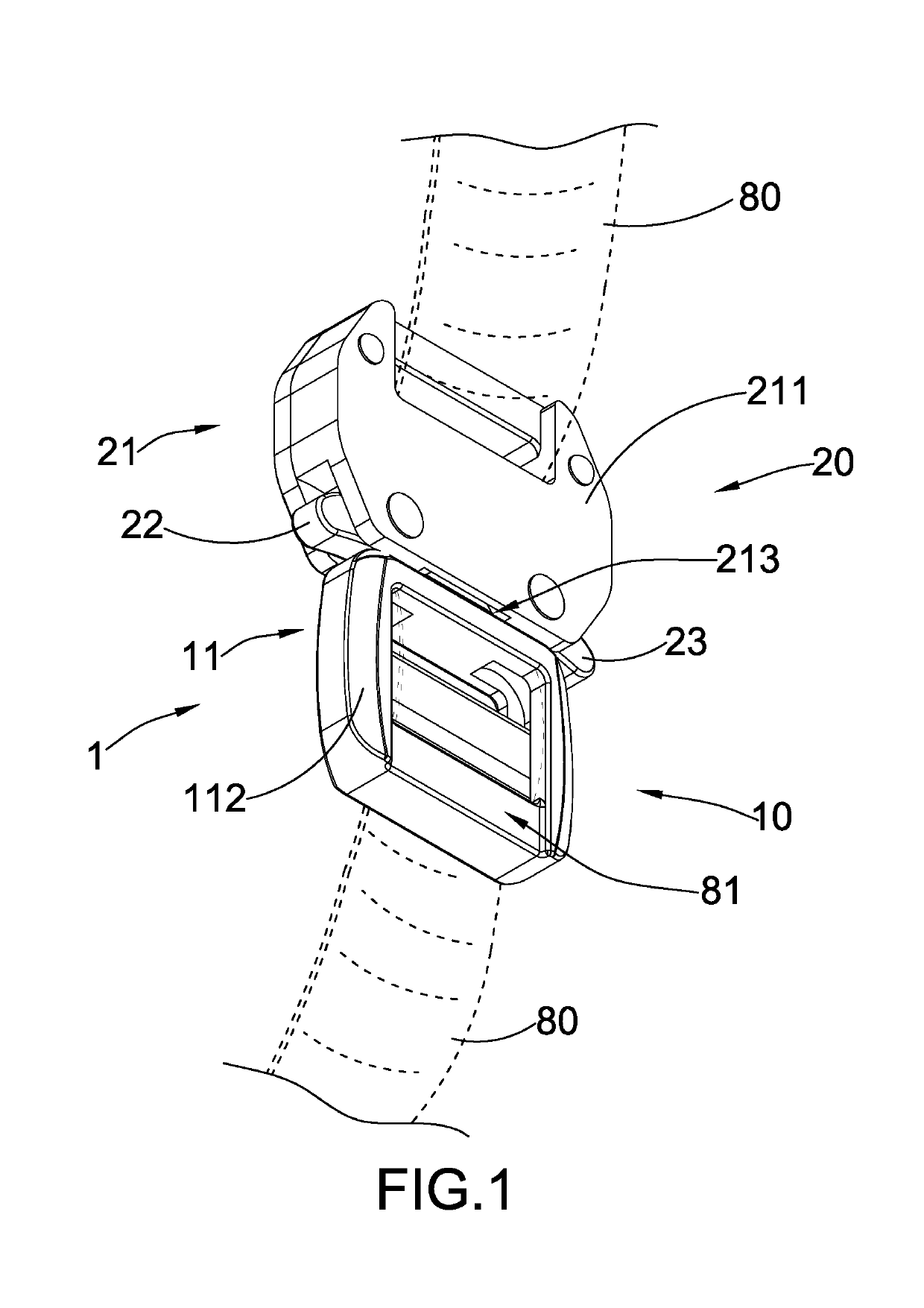
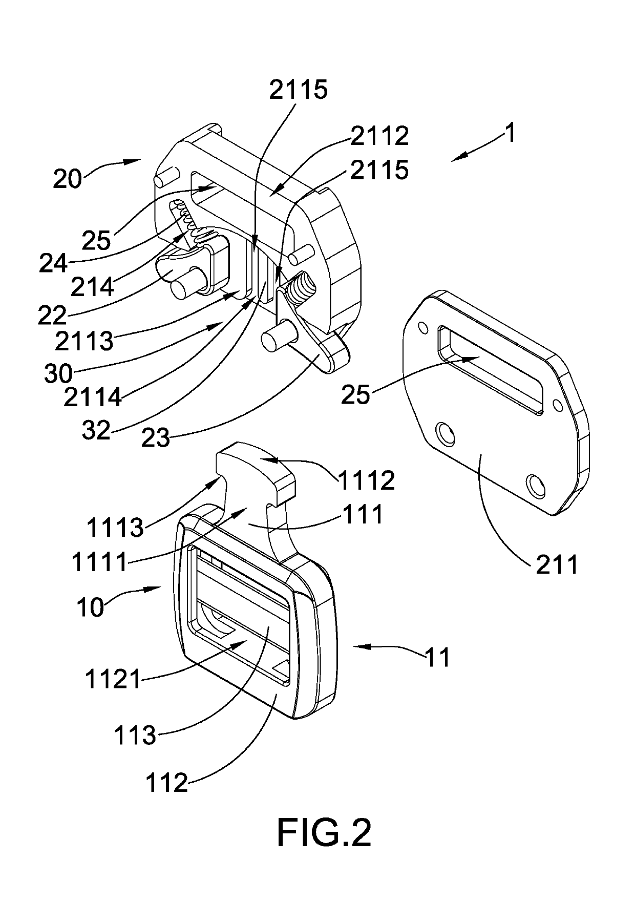
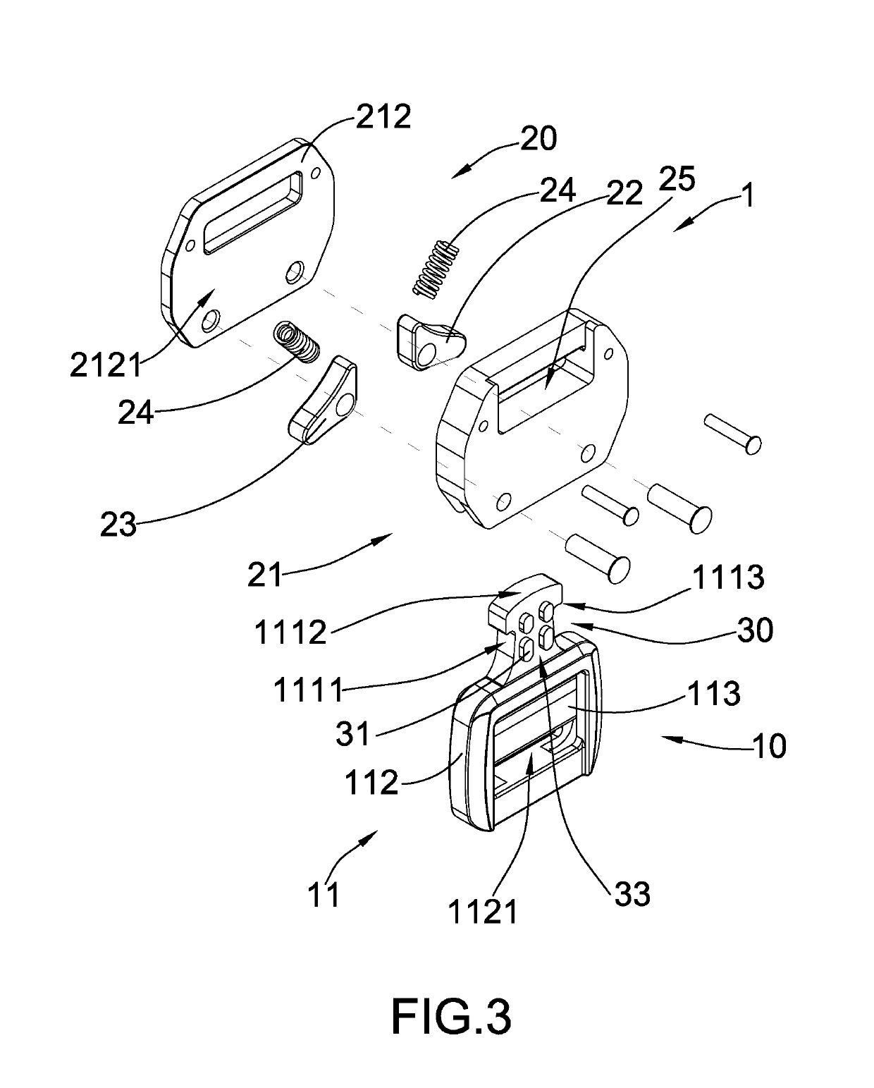
[0024]Referring to FIG. 1 to FIG. 7 of the drawings, a buckle assembly 1 according to a preferred embodiment of the present invention is illustrated. Broadly, the buckle assembly 1 comprises a first buckle member 10, a second buckle member 20, and a locking arrangement 30.

[0025]The first buckle member 10 may comprise a first buckle body 11 comprising an insertion member 111. The second buckle member 20 may comprise a second buckle body 21, a first buckle latch 22, a second buckle latch 23, and a plurality of resilient elements 24.

[0026]The second buckle body 21 may comprise a rear connecting piece 211, and a front connecting piece 212 attached on the rear connecting piece 211 to define a receiving slot 213 betwe...


PUM


Abstract

A buckle assembly includes a first buckle member having an insertion member, a second buckle member, a first buckle latch, a second buckle latch, a plurality of resilient elements, and a locking arrangement. The locking arrangement includes at least two locking protrusions and at least one guiding member. The locking protrusions are extended from one of the insertion member and the second buckle body, and are arranged to form a locking channel between the two locking protrusions. The guiding member is extended from the remaining one of the insertion member and the second buckle body, and is arranged to be inserted in the locking channel formed by the locking protrusions so as to retain the first buckle member to be locked with the second buckle member when the first buckle latch and the second buckle latch are in the locked position.

Description

BACKGROUND OF THE PRESENT INVENTIONField of Invention[0001]The present invention relates to a buckle, and more particularly to a buckle assembly which comprises a locking arrangement which is capable of providing an enhanced locking performance and convenient operation of the buckle assembly.Description of Related Arts[0002]A conventional buckle assembly, such as a buckle assembly for use with a webbing strap, usually comprises a first buckle member and a second buckle member detachably engaged with the first buckle member. The first buckle member may have an insertion member while the second buckle member may comprise a plurality of buckle latches and have a receiving slot formed at a position corresponding to the insertion member of the first buckle member. The receiving slot is shaped and sized to receive the insertion member so as to connect the first buckle member to the second buckle member. The buckle latches may be pivotally movable on the second buckle member to selectively...

Claims


Application Information

Patent Timeline
Patent Type & Authority Patents(United States)
IPC IPC(8): A44B11/25A44B11/00
CPCA44B11/25A44B11/00A44B11/2519A44B11/2573
Inventor HSU, FRANK
Owner HSU FRANK
Features
  • R&D
  • Intellectual Property
  • Life Sciences
  • Materials
  • Tech Scout
  • Unparalleled Data Quality
  • Higher Quality Content
  • 60% Fewer Hallucinations
Learn More