Interspinous implant insertion instrument with staggered path implant deployment mechanism

a technology of implant insertion instrument and deployment mechanism, which is applied in the field of spinal implant insertion instruments, can solve the problems of spinal canal narrowing and compression of spinal cord or nerve roots, pain and numbness in the back and legs, weakness and/or loss of balance,

Active Publication Date: 2019-09-24
SPINAL SIMPLICITY
View PDF55 Cites 4 Cited by
  • Summary
  • Abstract
  • Description
  • Claims
  • Application Information

AI Technical Summary

Benefits of technology

[0011]The insertion instrument may still further include a proximal end cap between a plunger knob and a proximal portion of the handle and a distal end cap between a distal portion of the handle and a knob of the hex nut driver. The proximal end cap can include at least one flexible tooth corresponding to a plurality of ratchet teeth of the handle. The at least one flexible tooth and plurality of ratchet teeth configured to auto-lock the plunger and plunger knob to the handle and prevent premature loosening. The distal end cap can include at least one flexible tooth corresponding to a plurality of ratchet teeth of the handle. The at least one flexible tooth and plurality of ratchet teeth configured to auto-lock the hex nut driver and the handle together and prevent premature loosening.

Problems solved by technology

Over time, the ligaments and bone that surround the spinal canal can thicken and harden, resulting in a narrowing of the spinal canal and compression of the spinal cord or nerve roots.
This condition is called spinal stenosis, which results in pain and numbness in the back and legs, weakness and / or a loss of balance.
While some patients may experience relief from symptoms of spinal stenosis with such treatments, many do not, and thus turn to surgical treatment.

Method used


Image

  • Interspinous implant insertion instrument with staggered path implant deployment mechanism
  • Interspinous implant insertion instrument with staggered path implant deployment mechanism
  • Interspinous implant insertion instrument with staggered path implant deployment mechanism

Examples


Embodiment Construction

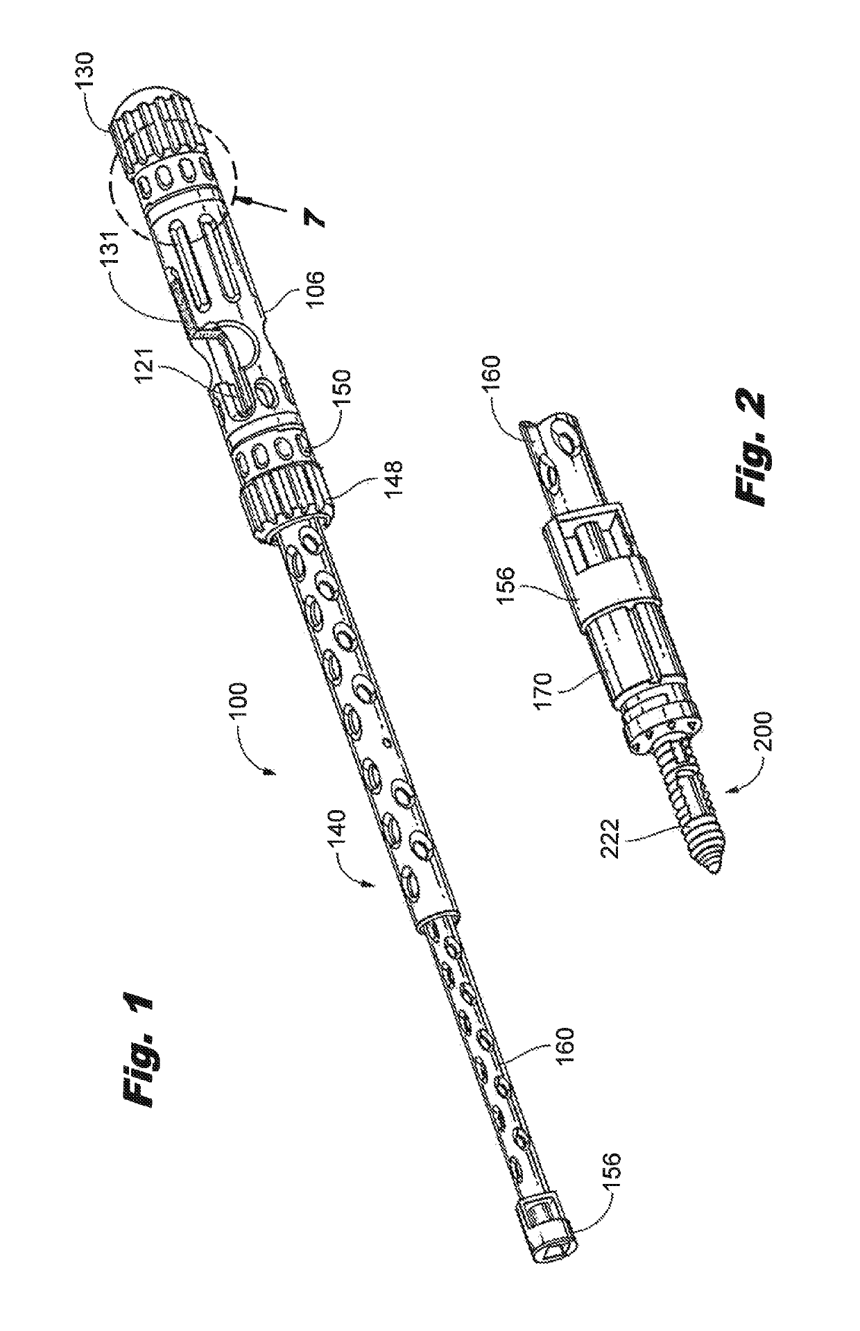
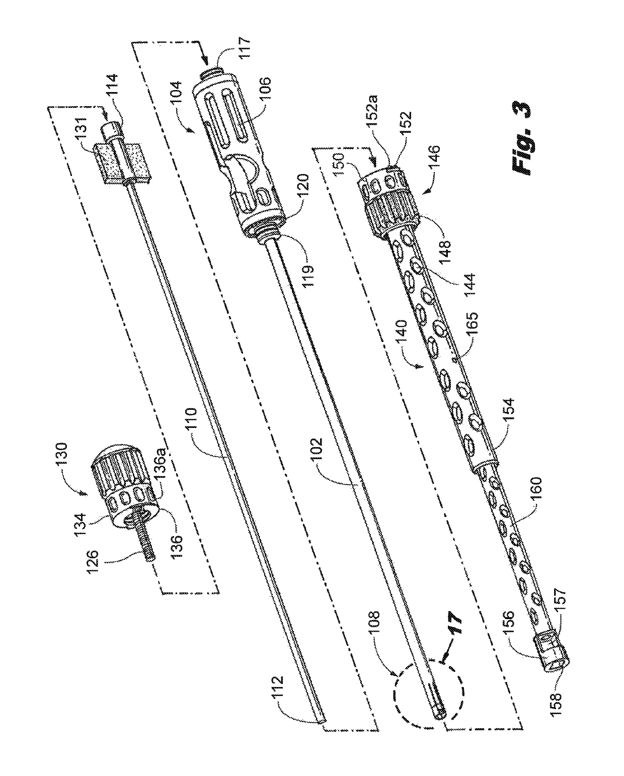
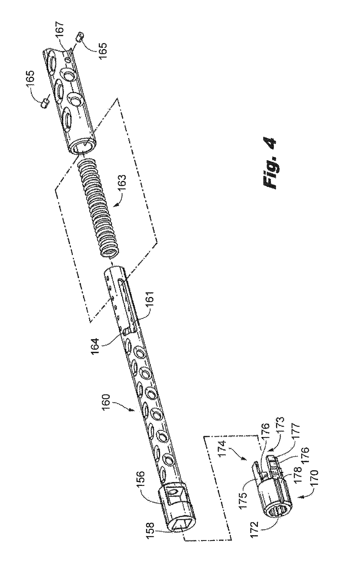
[0043]The present disclosure overcomes many of the prior art problems associated with instruments for inserting spinal implants and other devices such as cage spacers and the like. The advantages and other features of the instruments and methods disclosed herein will become more readily apparent to those having ordinary skill in the art from the following detailed description of certain preferred embodiments taken in conjunction with the drawings which set forth representative embodiments of the present invention and wherein like reference numerals identify similar structural elements.

[0044]All relative descriptions herein such as left, right, up, and down are with reference to the Figures, and not meant in a limiting sense. The illustrated embodiments can be understood as providing exemplary features of varying detail of certain embodiments, and therefore, features, components, modules, elements, and / or aspects of the illustrations can be otherwise combined, interconnected, sequenc...


PUM


Abstract

An insertion instrument for inserting an implant includes an elongated main body having a proximal handle and a distal portion that selectively couples to the implant. A plunger is slidably engaged in a central passage of the elongated main body configured to fix the implant to the elongated main body by selectively filling the central passage within the distal portion. A hex nut driver is concentrically located about the plunger and elongated main body to deploy an actuation plunger of the implant. The proximal handle portion of the main body includes a staggered path therethrough for accepting a tab of the plunger therein. Advancement and retraction of the plunger tab within the staggered path alternates the insertion instrument between an unlocked position configured to mount the implant on the distal portion of the elongated main body, a locked position configured to lock the implant on the distal portion, and a deployed position configured to secure the implant.

Description

CROSS-REFERENCE TO RELATED APPLICATIONS[0001]This application claims the benefit of and priority to U.S. Patent Application Ser. No. 62 / 322,390, filed Apr. 14, 2017, which is incorporated herein by reference in its entirety. The interspinous implant insertion instrument of the subject invention relates to the insertion instrument disclosed in commonly assigned U.S. Patent Application Publication 2014 / 0358186, the disclosure of which is incorporated herein by reference in its entirety.BACKGROUND OF THE INVENTION1. Field of the Invention[0002]The subject technology is directed to instruments for inserting spinal implants, and more particularly, to an insertion instrument that is easily assembled and disassembled for required cleaning while being able to effectively deploy an interspinous process implant for spinal stabilization, for percutaneous placement in a target interspinous process space, wherein the implant can also serve as a fusion cage spacer to treat lumbar spinal stenosis....

Claims


Application Information

Patent Timeline
Patent Type & Authority Patents(United States)
IPC IPC(8): A61B17/70A61F2/46A61B17/00
CPCA61B17/7065A61B17/7082A61B17/7068A61F2/4611A61F2002/4627A61F2002/4635A61B2017/00862A61F2002/4615
Inventor SNELL, DOUGLASBARNDS, ANNARIAFROCK, ADAM
Owner SPINAL SIMPLICITY
Why Eureka
Try Eureka