Speed reducer

a technology of speed reducer and reducer, which is applied in the direction of toothed gearings, gearings, control devices, etc., can solve the problems of harmonic drive reducers that cannot withstand, the cost of rv-e series reducers is high, and the difficulty of driving a large-sized load, etc., to achieve the effect of high volume, weight and cos

Active Publication Date: 2019-09-24
DELTA ELECTRONICS INC
View PDF4 Cites 5 Cited by
  • Summary
  • Abstract
  • Description
  • Claims
  • Application Information

AI Technical Summary

Benefits of technology

[0007]An object of the present invention provides a speed reducer. The speed reducer is an epicycloid-epicycloid speed reducer or a hypocycloid-hypocycloid speed reducer. The speed reducer comprises a rotating wheel, a first roller assembly and a second roller assembly. The rotating wheel comprises a convex structure and a concave structure. The convex structure is contacted with plural first rollers of the first roller assembly, and the concave structure is contacted with plural second rollers of the second roller assembly. The cooperation of the rotating wheel and associated components can achieve the speed reducing purpose. By the speed reducer of the present invention, the problems of the conventional RV reducer (e.g., high volume, weight and cost) and the problems of the conventional harmonic drive reducer (e.g., the deformation of the flex spline and the teeth difference friction) will be overcome.

Problems solved by technology

In other words, it is difficult to drive a large-sized load.
However, since the RV-E series reducer has larger volume and weight and has many components, the cost of the RV-E series reducer is high.
However, since the rigidity of the flex element of the harmonic drive reducer is lower than the metallic element, the harmonic drive reducer is unable to withstand high impact and has a problem of causing teeth difference friction.

Method used


Image

  • Speed reducer
  • Speed reducer
  • Speed reducer

Examples


first embodiment

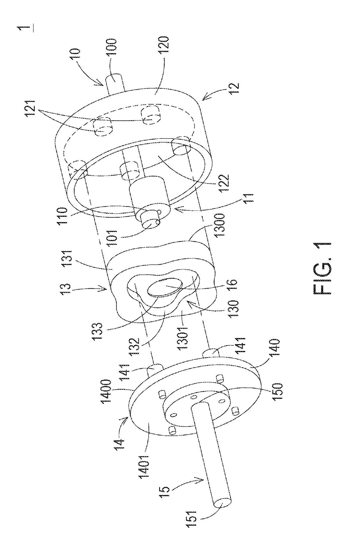
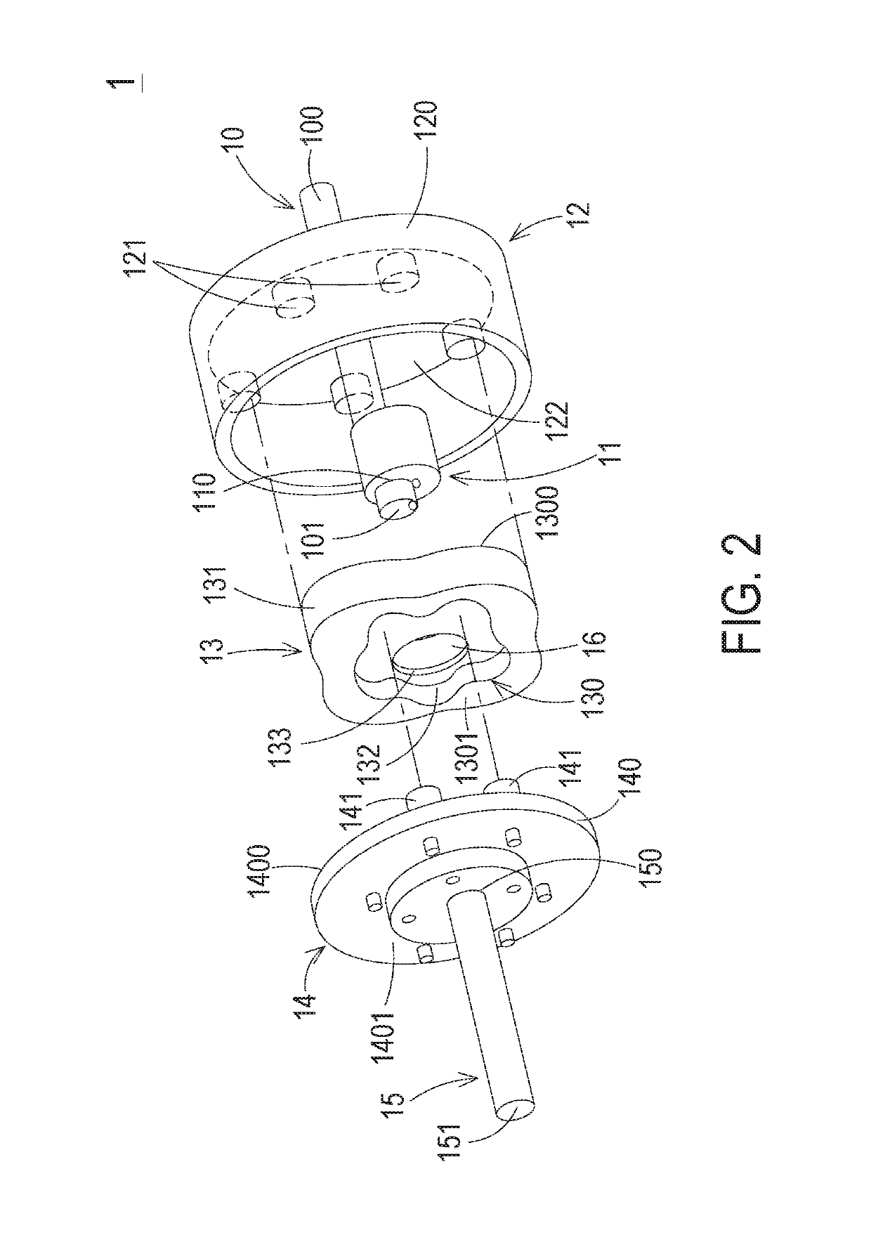
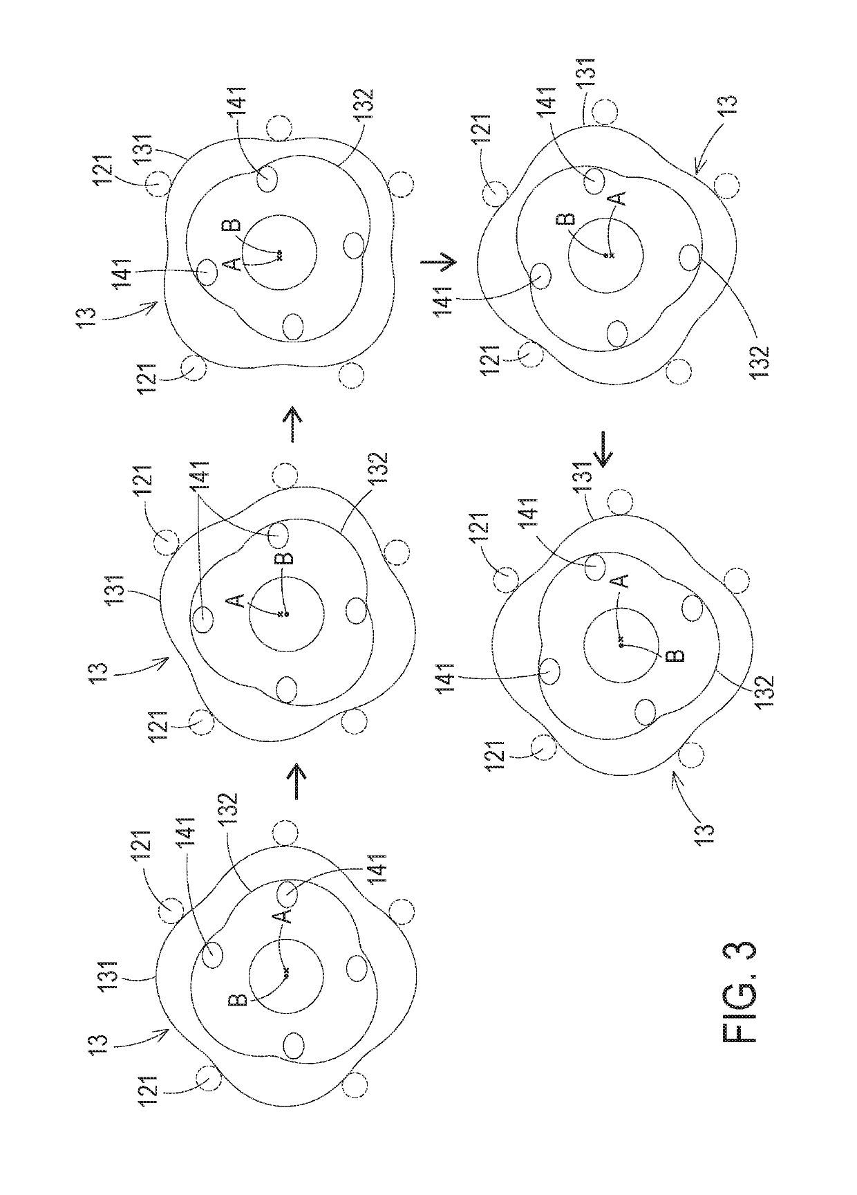
[0089]As mentioned above, the first rollers 121 and the outer teeth of the convex structure 131 cooperate with each other, and the second rollers 141 and the inner teeth of the concave structure 132 cooperate with each other. Consequently, the speed reducer 1 is a two-stage cycloid speed reducer. Moreover, both of the convex structure 131 and the concave structure 132 are formed on the single rotating wheel 13. In comparison with the conventional two-stage speed reducer comprising two rotating wheels, the volume of the speed reducer 1 is reduced. In the architecture of the two-stage cycloid speed reducer, the first rollers 121 and the outer teeth of the convex structure 131 are collaboratively formed as the first-stage cycloid structure of the speed reducer 1, and the second rollers 141 and the inner teeth of the concave structure 132 are collaboratively formed as the second-stage cycloid structure of the speed reducer 1. Since the number of the first rollers 121 is at least one mor...

second embodiment

[0094]FIG. 21 is a schematic exploded view illustrating a speed reducer according to the present invention. The speed reducer 1′ can be applied to motors, machine tools, robotic arms, automobiles, motorcycles or other motive machines in order to provide a speed reducing function, wherein the speed reducer 1′ is a two-stage cycloid speed reducer. As shown in FIG. 21, the speed reducer 1′ comprises a first transmission shaft 10′, an eccentric wheel 11′, a first roller assembly 12′, a rotating wheel 13′, a second roller assembly 14′, a second transmission shaft 15′ and a bearing 16′.

[0095]Preferably but not exclusively, the first transmission shaft 10′ is a shaft that is made of metallic material or alloy. The first transmission shaft 10′ has a first end 100′ and a second end 101′. The first end 100′ is a power input end for receiving an input power from a motor (not shown). The eccentric wheel 11′ is a circular disc structure that is made of metallic material or alloy. Moreover, the e...


PUM


Abstract

A speed reducer includes a first transmission shaft, an eccentric wheel, a first roller assembly, a rotating wheel, a second roller assembly and a second transmission shaft. The rotating wheel includes a main body and an axle hole. The main body includes a convex structure and a concave structure. The convex structure is protruded from an outer periphery of the main body and has outer teeth. The outer teeth are contacted with the corresponding first rollers. The concave structure is concavely formed in a surface of the main body and includes inner teeth. The inner teeth are contacted with plural second rollers of the second roller assembly. The speed reducer of the present invention is an epicycloid-epicycloid speed reducer or a hypocycloid-hypocycloid speed reducer. Since the speed reducer is designed to have four operating situations, the speed reducer can have various reduction ratios.

Description

CROSS-REFERENCE TO RELATED APPLICATION[0001]This application claims the benefit of U.S. Provisional Application No. 62 / 462,612 filed on Feb. 23, 2017, and entitled “SPEED REDUCER”, the entirety of which is hereby incorporated by reference. This application is also a continuation-in-part application of U.S. application Ser. No. 14 / 930,026 filed on Nov. 2, 2015, and entitled “SPEED REDUCER”, the entirety of which is hereby incorporated by reference.FIELD OF THE INVENTION[0002]The present invention relates to a speed reducer, and more particularly to a speed reducer with the benefits of a RV reducer and a harmonic drive reducer and having a high reduction ratio.BACKGROUND OF THE INVENTION[0003]Generally, a motor is operated at a high speed and a low torsion force. In other words, it is difficult to drive a large-sized load. Consequently, for allowing the motor to drive a heavy object, a speed reducer is used for reducing the rotating speed of the motor and increasing the torsion force....

Claims


Application Information

Patent Timeline
Patent Type & Authority Patents(United States)
IPC IPC(8): F16H1/32B60K17/04
CPCF16H1/32B60K17/04
Inventor HO, YI-LUNTSAI, CHING-HSIUNGWU, JIA-MING
Owner DELTA ELECTRONICS INC
Why Eureka
Try Eureka