System and method for textile positioning

a technology for positioning and textiles, applied in the field of positioning and securing textiles, can solve the problems of reducing efficiency, reducing output, and inefficiency of the manufacturing process of prior art looms and other apparatuses for manufacturing circular preforms, and achieve the effect of increasing fiber volum

Inactive Publication Date: 2011-11-10
THE BF GOODRICH CO
View PDF5 Cites 40 Cited by
  • Summary
  • Abstract
  • Description
  • Claims
  • Application Information

AI Technical Summary

Benefits of technology

[0012]In order to address the deficiencies outlined above, various embodiments of a circular needle loom comprise a stationary bed plate for receiving a spiral textile. Engagement members may be disposed next to the stationary bed plate, such that they interface with a positional structure of the spiral textile that is used to rotate the spiral textile around the stationary bed plate. A conical roller deploys the spiral textile on the stationary bed plate. The c...

Problems solved by technology

Significantly, prior art looms and other apparatuses for manufacturing circular preforms suffer from inefficiencies in the manufacturing process.
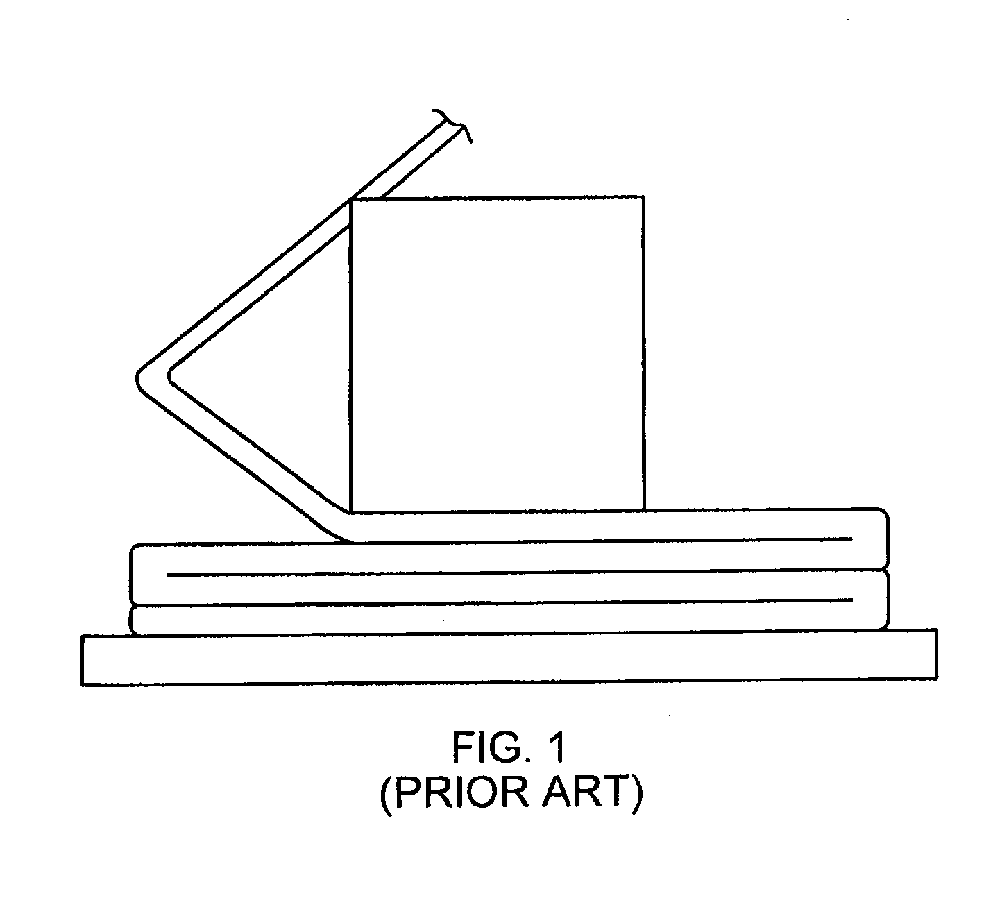
However, maintenance and cleaning of the brush bed plate, and removal of the finished preform from the bed plate create extra steps in the needling process.
These extra steps, among other reasons, substantially add to the time required to manufacture the preform, resulting in reduced efficiency, lower output and increased cost.
Such brush bed plates are therefore generally not suitable for high production rates, and it is desirable to develop a system and method for increasing the efficiency of the manufacturing process to result in higher production rates and reduced costs
Furthermore the brush bed plate does not always provide sufficient anchorage of the bottom layers, resulting in some cases of preform transport interruption during fabrication.
Additionally, existing systems and methods for manufacturing circular preforms may...

Method used


Image

  • System and method for textile positioning
  • System and method for textile positioning
  • System and method for textile positioning

Examples


Embodiment Construction

[0052]The detailed description of various embodiments herein makes reference to the accompanying drawing figures, which show various embodiments and implementations thereof by way of illustration and its best mode, and not of limitation. While these embodiments are described in sufficient detail to enable those skilled in the art to practice the embodiments, it should be understood that other embodiments may be realized and that logical, electrical, and mechanical changes may be made without departing from the spirit and scope of the invention. Furthermore, any reference to singular includes plural embodiments, and any reference to more than one component or step may include a singular embodiment or step.

[0053]Also, any reference to attached, fixed, connected or the like may include permanent, removable, temporary, partial, full and / or any other possible attachment option. Additionally, any reference to without contact (or similar phrases) may also include reduced contact or minimal...


PUM

PropertyMeasurementUnit
Diameteraaaaaaaaaa
Diameteraaaaaaaaaa
Diameteraaaaaaaaaa

Abstract

A circular needle loom comprises a stationary bed plate for receiving a spiral textile. Engagement members may be disposed next to the stationary bed plate, such that the engagement members interface with a positional structure of the spiral textile that is used to position and rotate the spiral textile around the stationary bed plate. A conical roller deploys the spiral textile on the stationary bed plate. The engagement members rotate the spiral textile around the stationary bed plate until a predetermined number of layers are deposited on the stationary bed plate.
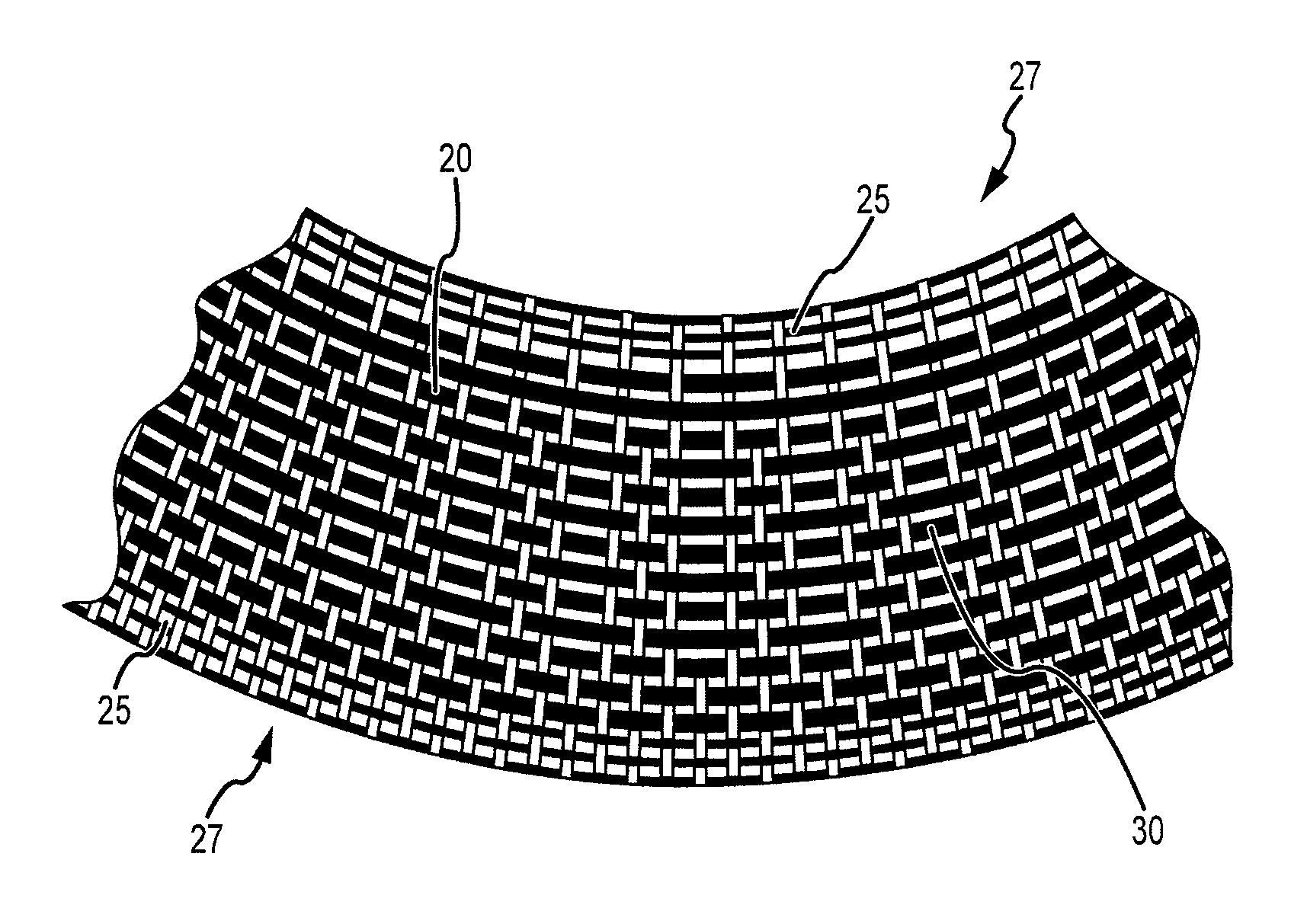
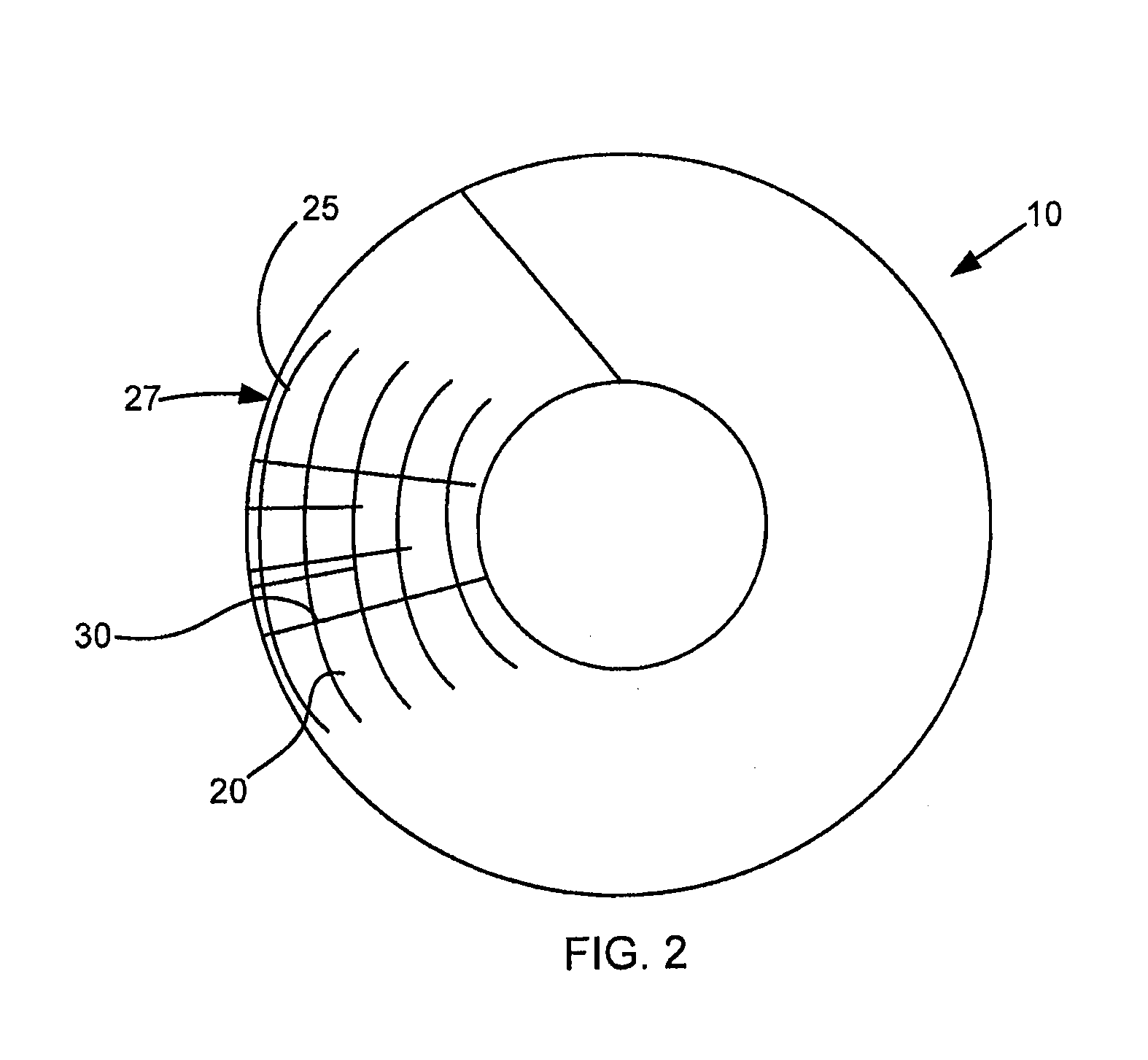
A spiral textile comprises a weft tow that extends from an inside diameter to an outside diameter, and a positional structure, such as a sacrificial edge and/or loop, is located next to and/or is attached to the weft tow. The positional structure facilitates positioning the spiral textile in a desired manner with respect to the circular needle loom in order to create a needled preform.

Description

FIELD OF INVENTION[0001]This invention generally relates to positioning and securing a textile, and more particularly, to systems and methods for positioning and securing a spiral textile on a rotational bed plate or entraining a textile on a stationary bed plate to needle the spiral textile into a circular preform.BACKGROUND OF THE INVENTION[0002]Carbon / carbon (“C / C”) parts are employed in various industries. An exemplary use for C / C parts includes using them as friction disks such as aircraft brake disks, race car brake disks, clutch disks, and the like. C / C brake disks are especially useful in such applications because of the superior high temperature characteristics of C / C material. In particular, the C / C material used in C / C parts is a good conductor of heat and thus is able to dissipate heat away from the braking surfaces that is generated in response to braking. C / C material is also highly resistant to heat damage, and is thus capable of sustaining friction between brake surf...

Claims


Application Information

Patent Timeline
IPC IPC(8): D03D15/00B32B5/26D03D41/00D04H1/46D04H18/00D03D15/68
CPCB29B11/16F16D69/023D04H18/02D04H1/48D03D1/00D03D3/00D03D15/06D03D15/12D06H7/00Y10T442/348Y10T442/30B29C70/32B29C70/386B65H75/20B65H75/24D03D3/08D04H18/00D03D15/68
Inventor LECOSTAOUEC, JEAN-FRANCOIS
Owner THE BF GOODRICH CO
Why Eureka
Try Eureka