Thin Film Battery Fabrication With Mask-Less Electrolyte Deposition

a thin film battery and fabrication process technology, applied in the direction of cell components, final product manufacturing, sustainable manufacturing/processing, etc., can solve the problems of shadow mask warping, loss of mask alignment, and still need to overcome, so as to reduce the cost and complexity of thin film battery (tfb), improve the manufacturability of tfb, and high volume and throughput.

Inactive Publication Date: 2012-12-20
APPLIED MATERIALS INC
View PDF5 Cites 37 Cited by
  • Summary
  • Abstract
  • Description
  • Claims
  • Application Information

AI Technical Summary

Benefits of technology

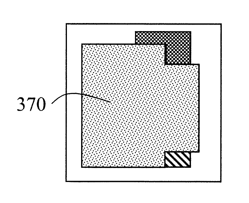
[0006]The concepts and methods of the present invention are intended to permit reduction of the cost and complexity of thin film battery (TFB) high volume manufacturing (HVM) by eliminating the use of shadow masks for electrolyte deposition. Furthermore, embodiments of the present invention may improve the manufacturability of TFBs on large area substrates at high volume and throughput. This may significantly reduce the cost for broad market applicability as well as provide yield improvements and improved pattern alignment accuracy. According to aspects of the invention, these and other advantages are achieved with the use of a selective laser ablation process, where the laser patterning process removes the blanket electrolyte layer in selected areas while leaving the current collector layers below intact.

Problems solved by technology

However, there are challenges that still need to be overcome to allow cost effective high volume manufacturing (HVM) of TFBs.
The electrolyte layer (e.g. LiPON) is the most challenging TFB device layer to deposit using a shadow mask because of the deposition process—radio frequency physical vapor deposition (RF PVD) magnetron sputtering—and also due to the electrolyte layer typically being one of the thickest device layers and typically requiring a longer deposition time than other layers.
The substrate temperature increases with deposition time and RF power, which can result in warping of the shadow mask and loss of mask alignment.
However, the additional backside magnets are found to interact with the RF PVD process, which dramatically reduces TFB yields.
Furthermore, Kapton® tape generally cannot withstand the higher temperature and higher power processes that are required for higher deposition rates (and thus higher throughput), therefore using Kapton® necessitates the use of lower deposition rate processes to avoid shadow mask alignment shifts and inaccurate pattern transfer.

Method used


Image

  • Thin Film Battery Fabrication With Mask-Less Electrolyte Deposition
  • Thin Film Battery Fabrication With Mask-Less Electrolyte Deposition
  • Thin Film Battery Fabrication With Mask-Less Electrolyte Deposition

Examples


Embodiment Construction

[0018]Embodiments of the present invention will now be described in detail with reference to the drawings, which are provided as illustrative examples of the invention so as to enable those skilled in the art to practice the invention. The drawings provided herein include representations of devices and device process flows which are not drawn to scale. Notably, the figures and examples below are not meant to limit the scope of the present invention to a single embodiment, but other embodiments are possible by way of interchange of some or all of the described or illustrated elements. Moreover, where certain elements of the present invention can be partially or fully implemented using known components, only those portions of such known components that are necessary for an understanding of the present invention will be described, and detailed descriptions of other portions of such known components will be omitted so as not to obscure the invention. In the present specification, an emb...


PUM

PropertyMeasurementUnit
absorption depthaaaaaaaaaa

Abstract

A method of fabricating a thin film battery may include a blanket deposition of an electrolyte layer followed by selective laser patterning of the electrolyte layer. Some or all of the other device layers may be in situ patterned layers—formed using shadow masks.

Description

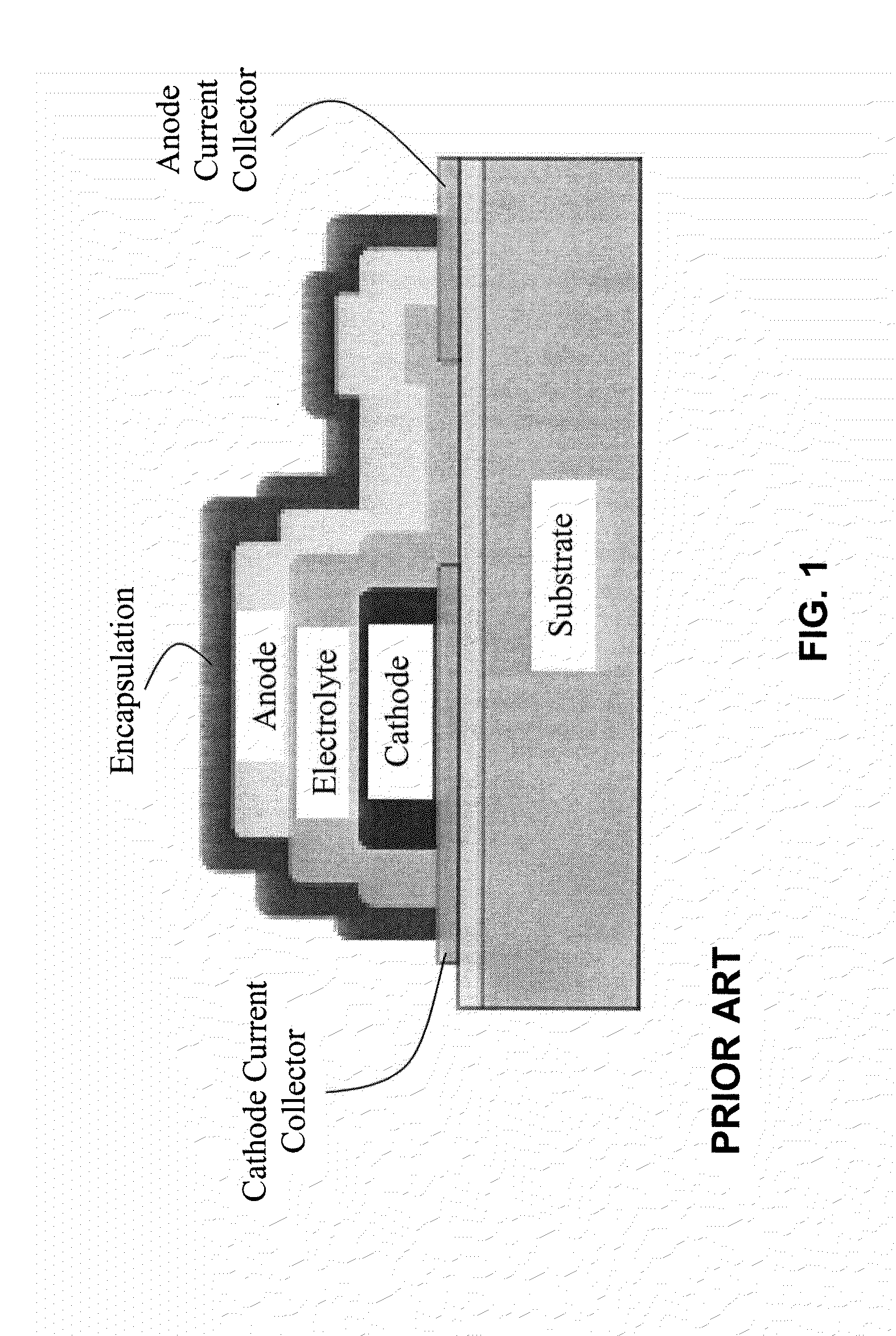
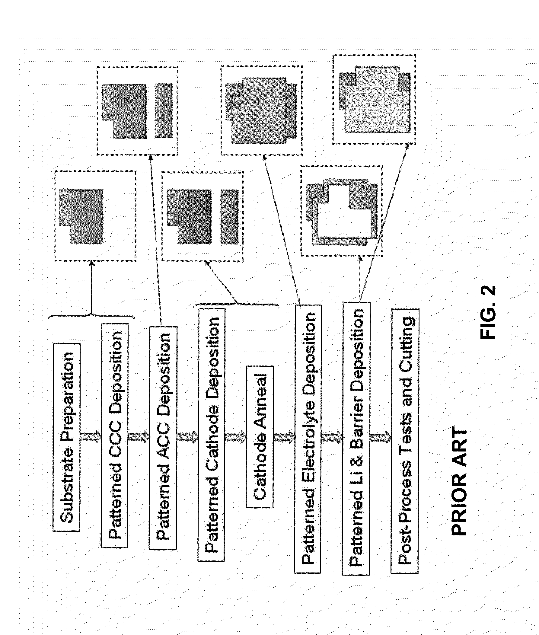
CROSS-REFERENCE TO RELATED APPLICATIONS[0001]This application claims the benefit of U.S. Provisional Application No. 61 / 498,490 filed Jun. 17, 2011, incorporated herein by reference in its entirety.[0002]This invention was made with U.S. Government support under Contract No. W15P7T-10-C-H604 awarded by the U.S. Department of Defense. The Government has certain rights in the invention.FIELD OF THE INVENTION[0003]Embodiments of the present invention relate to mask-less fabrication processes for thin film batteries.BACKGROUND OF THE INVENTION[0004]Thin film batteries (TFBs) have been projected to dominate the micro-energy applications space. TFBs are known to exhibit several advantages over conventional battery technology such as superior form factors, cycle life, power capability and safety. FIG. 1 shows a cross-sectional representation of a typical thin film battery (TFB) and FIG. 2 shows a flow diagram for TFB fabrication along with corresponding plan views of the patterned TFB laye...

Claims


Application Information

Patent Timeline
Patent Type & Authority Applications(United States)
IPC IPC(8): H01M4/04
CPCH01M4/0426H01M4/0471H01M4/139H01M4/70H01M10/052H01M10/0562H01M10/0585H01M6/40H01M10/0436H01M10/0525H01M50/403H01M50/463Y02E60/10Y02P70/50
Inventor SONG, DAOYINGJIANG, CHONGKWAK, BYUNG-SUNG LEO
Owner APPLIED MATERIALS INC
Why Eureka
Try Eureka