In-built antenna for mobile communication device

a mobile communication device and in-built antenna technology, applied in the direction of antenna earthings, substantially flat resonant elements, resonance antennas, etc., can solve the problems of difficult to overcome the disadvantages above disadvantages of conventional in-built antennas, the need for high-performance connectors tends to significantly increase the antenna cost, and the loss of antenna patterns and radio transceiver components caused by connectors, so as to reduce the cost of connectors, and reduce the effect o

Inactive Publication Date: 2005-04-12
TELEFON AB LM ERICSSON (PUBL)
View PDF18 Cites 92 Cited by
  • Summary
  • Abstract
  • Description
  • Claims
  • Application Information

AI Technical Summary

Benefits of technology

The present invention provides an in-built antenna which eliminates the conventional antenna connector between the antenna pattern and radio signal transmit and receive components described above. Thus, the costs associated with such connectors, as well as losses between the antenna pattern and the radio transceiver components caused by the connector, are likewise eliminated. Moreover, manufacturability of the antenna, and in particular the manufacture of the radiator or antenna pattern, is significantly enhanced as described hereinafter in further detail.

Problems solved by technology

However, the need for high performance connectors tends to significantly increase antenna costs.
Moreover, the connectors tend to cause losses in transmission and reception of radio signals.
The above disadvantages in conventional in-built antennas are difficult to overcome.
A mobile phone housing has very limited interior space or volume, and must be able to contain other components in addition to the in-built antenna.

Method used


Image

  • In-built antenna for mobile communication device
  • In-built antenna for mobile communication device
  • In-built antenna for mobile communication device

Examples


Embodiment Construction

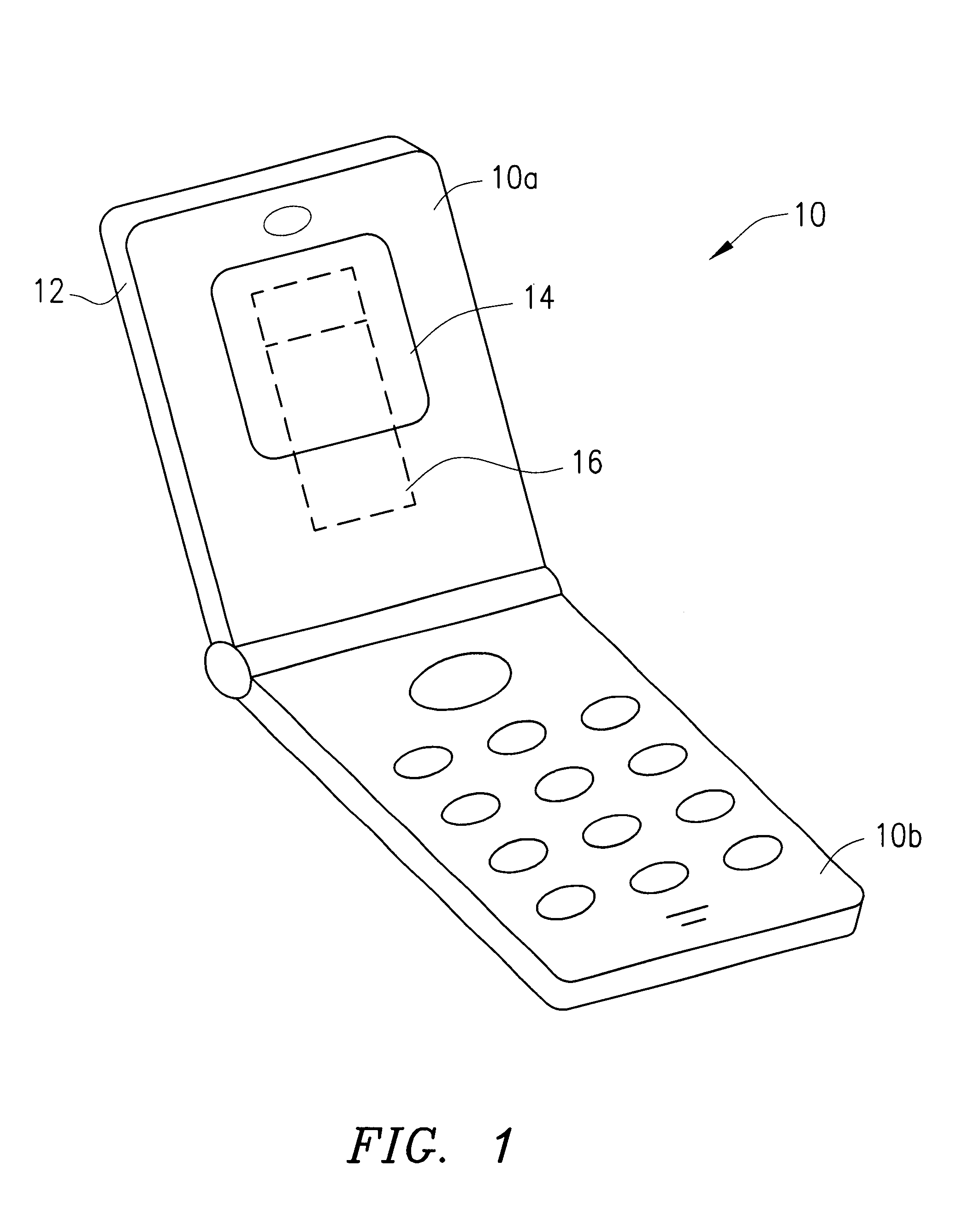
Referring to FIG. 1, there is shown a foldable “clam shell” mobile phone 10 comprising upper and lower phone members 10a and 10b, respectively. Upper phone member 10a is provided with a case or housing 12 for protectively enclosing certain electronic components (not shown). A display window 14 is included in case 12 to enable a phone user to view text or pictorial matter generated by a conventional display device (not shown) located behind window 14.

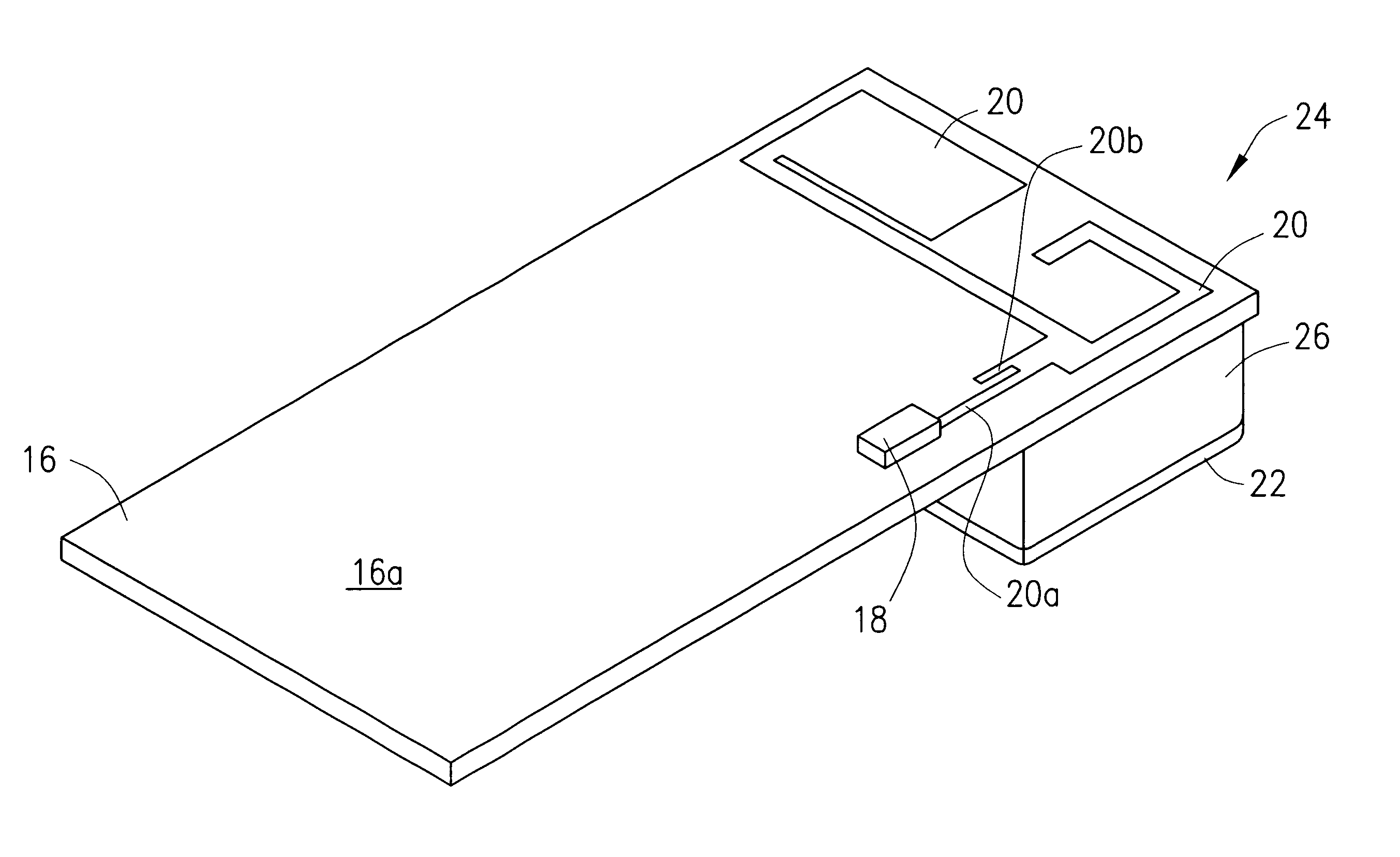
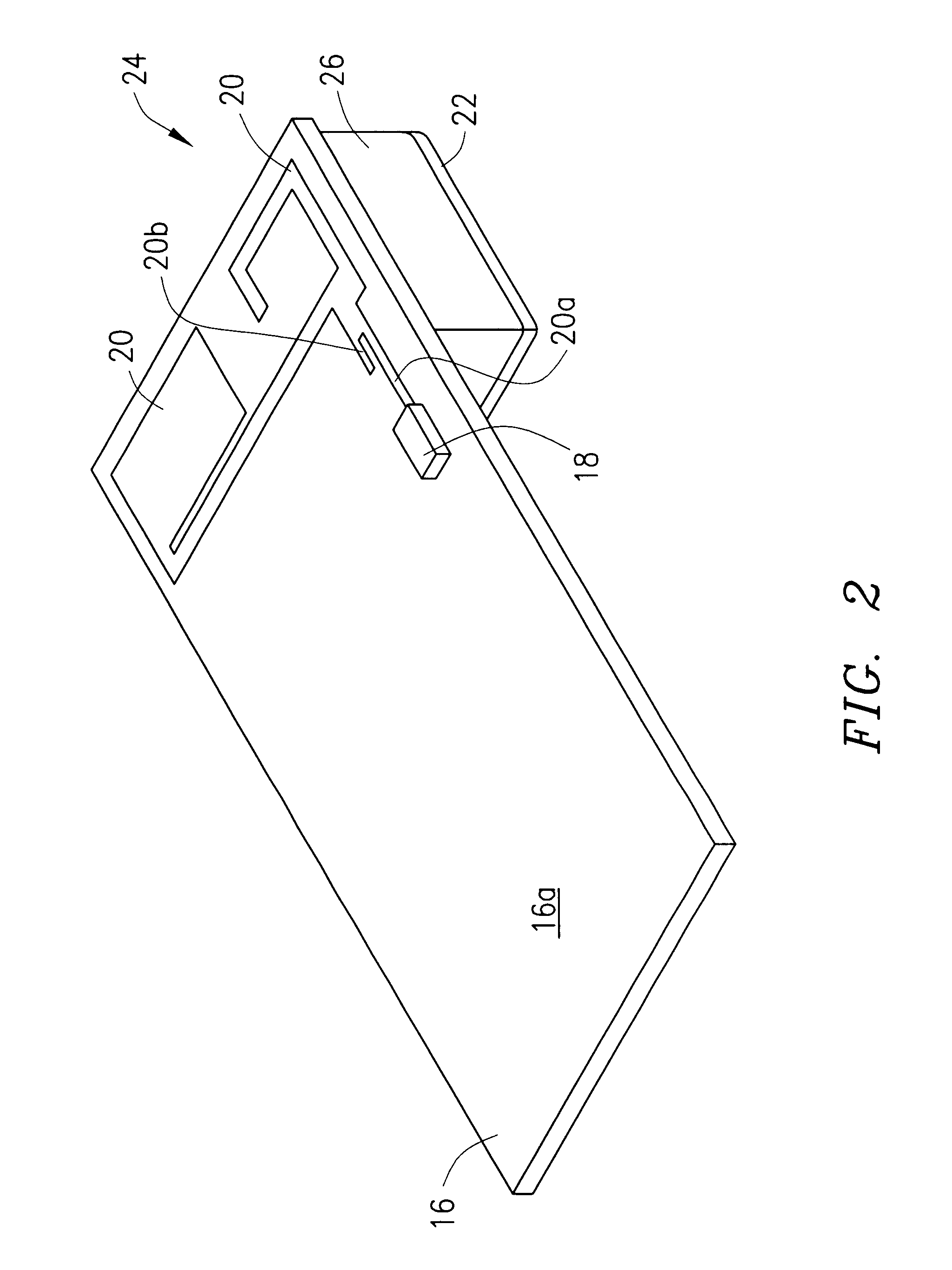
Referring further to FIG. 1, there is shown a main printed circuit board 16 fixably positioned within upper phone member 10a to supportably mount the display behind window 14. Circuit board 16 also supports electronic components (not shown in FIG. 1) required for the transmission and reception of radio signals during operation of mobile phone 10. As described hereinafter, main printed circuit board 16 is also used to mount the antenna required for operation of phone 10, the antenna comprising an in-built antenna contained entirely within...


PUM


Abstract

An in-built antenna is provided for a mobile phone or other communication device having a main printed circuit board contained within a case, wherein components for transmitting and receiving radio signals are mounted on the main circuit board. An antenna pattern or radiator is etched on the printed circuit board surface mounting the components, in electrical connection with the components, using the same process employed to form the components and connections between them. A ground plane is mounted to the opposing surface of the main printed circuit board, in facing, spaced-apart parallel relationship with the antenna pattern and in spaced-apart parallel relationship with the main printed circuit board.

Description

BACKGROUND OF THE INVENTIONThe invention disclosed and claimed herein generally pertains to an antenna configuration for a mobile communication device such as a mobile telephone. More particularly, the invention pertains to an in-built antenna, that is, an antenna of the above type which is contained entirely within the case or housing of the communication device. Even more particularly, the invention pertains to an antenna of the above type which reduces cost and communication losses, and is characterized by enhanced manufacturability.In designing mobile phones, it is frequently desirable to place or enclose the antenna entirely within the interior of the phone case. An arrangement of this type, referred to in the art as an in-built antenna, comprises a radiator or antenna pattern and an antenna ground plane. Typically, the antenna pattern is located above the ground plane, in spaced-apart relationship. The ground plane usually comprises one of the layers of the main printed circui...

Claims


Application Information

Patent Timeline
Patent Type & Authority Patents(United States)
IPC IPC(8): H01Q1/38H01Q1/24H01Q13/08H01Q9/40
CPCH01Q1/243H01Q1/38H01Q5/371H01Q9/0407H01Q1/48
Inventor BEGIC, STJEPAN
Owner TELEFON AB LM ERICSSON (PUBL)
Why Eureka
Try Eureka