Parallel Circuit of Accumulator Lines

a parallel circuit and accumulator technology, applied in the direction of electric vehicles, battery/fuel cell control arrangements, transportation and packaging, etc., can solve the problems of failure of the entire system, car breakdown, safety problems, etc., and achieve the effect of reducing the cost and electric loss of the accumulator

Active Publication Date: 2012-08-16
ROBERT BOSCH GMBH
View PDF4 Cites 8 Cited by
  • Summary
  • Abstract
  • Description
  • Claims
  • Application Information

AI Technical Summary

Benefits of technology

[0006]An object of the present invention is therefore to provide a circuit for connecting at least two accumulator lines in one accumulator, with the aid of which costs and electric losses in the accumulator may be reduced.

Problems solved by technology

The backdrop of these high demands is that a failure of the accumulator may result in a failure of the entire system.
For example, a traction battery failure in an electric vehicle results in a so-called “car breakdown.” This may even result in safety problems.
However, the costs of the circuit breakers in main contactors 42, 44, 54, 56 are very high.

Method used


Image

  • Parallel Circuit of Accumulator Lines
  • Parallel Circuit of Accumulator Lines

Examples


Embodiment Construction

[0024]Specific embodiments of the present invention are described in detail below with reference to the figures.

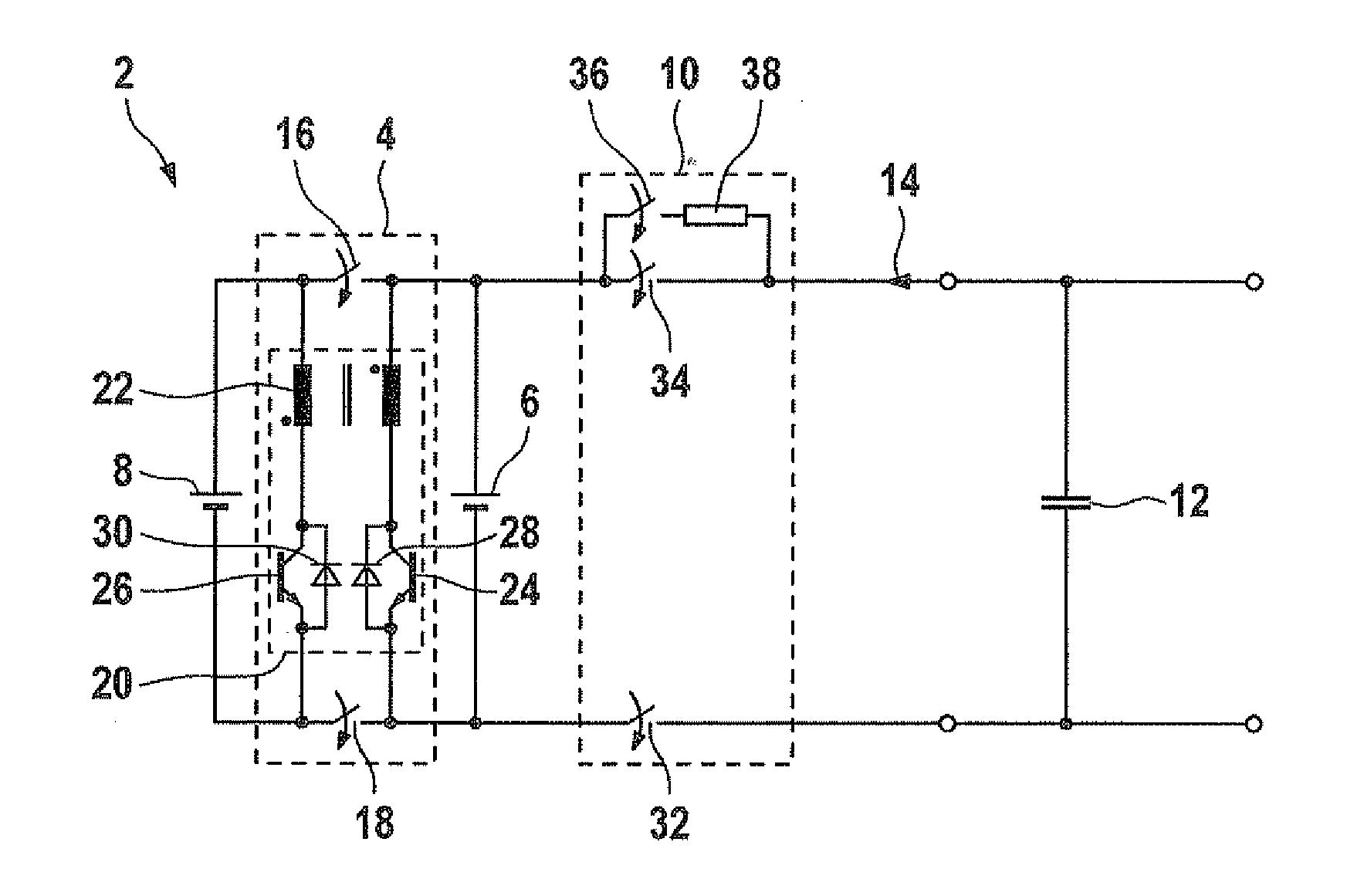
[0025]FIG. 1 shows a schematic circuit diagram of an accumulator 2 with an exemplary embodiment of a circuit 4 according to the present invention.

[0026]In accumulator 2, a first accumulator line 6 is connected in parallel to a second accumulator line 8 via circuit 4 according to the present invention. Furthermore, a DC link capacitor 12 as the electrical consumer having an input capacitance is connected in parallel to first accumulator line 6 via a protective circuit 10. Thus, an electric current 14 may be charged and discharged by accumulator 2 via DC link capacitor 12.

[0027]Circuit 4 according to the present invention has a first switch 16 and a second switch 18 in order to disconnect and connect the parallel connection between the two accumulator lines 6, 8. For the two accumulator lines 6, 8 to have a uniform voltage level in a separated state, a bidirectional switchin...


PUM


Abstract

A circuit for connecting a first accumulator line to a second accumulator line from an accumulator is described. The accumulator is provided for charging and discharging electrical energy via the accumulator lines. Each accumulator line has a positive pole and a negative pole for charging and discharging electrical energy. The circuit has at least one first switch which is provided for disconnecting and connecting two similar poles of the two accumulator lines.

Description

FIELD OF THE INVENTION[0001]The present invention relates to a circuit for connecting a first accumulator line to a second accumulator line from an accumulator, an accumulator for charging and discharging electrical energy via a DC link capacitor and a vehicle electrical system for supplying electrical consumers in a motor vehicle with electrical energy from an accumulator.BACKGROUND INFORMATION[0002]It may be expected that, in the future, for stationary applications, such as wind power plants, as well as in vehicles, such as hybrid or electric vehicles, new accumulator systems will be increasingly used which will be subjected to very high demands with respect to their reliability. The backdrop of these high demands is that a failure of the accumulator may result in a failure of the entire system. For example, a traction battery failure in an electric vehicle results in a so-called “car breakdown.” This may even result in safety problems. For example, accumulators are used in wind p...

Claims


Application Information

Patent Timeline
Patent Type & Authority Applications(United States)
IPC IPC(8): H02J7/00
CPCB60L11/1853B60L11/1855Y02T10/7061Y02T10/7005B60L11/1864B60L58/18B60L58/19B60L58/21Y02T10/70
Inventor BUTZMANN, STEFAN
Owner ROBERT BOSCH GMBH
Why Eureka
Try Eureka