Power tool with a DC brush motor and with a second power source

a brush motor and power tool technology, applied in the direction of motor/generator/converter stopper, motor/electric converter control, starter details, etc., can solve the problems of reducing the work time from a single charge of the dc power source (battery), requiring low speed operation, and reducing the cost of adding stages to the gearbox. , to achieve the effect of reducing the loss and cost of the gearbox

Active Publication Date: 2013-04-09
JOHNSON ELECTRIC SA
View PDF12 Cites 10 Cited by
  • Summary
  • Abstract
  • Description
  • Claims
  • Application Information

AI Technical Summary

Benefits of technology

[0016]Advantages of embodiments of the present invention include that different brushes and corresponding combinations of the power sources or the resistors can be selected by the switching device so that the motor can operate in different speed modes, therefore the stage number of the following gearboxes can be decreased so that losses and cost on the gearboxes can be reduced.

Problems solved by technology

For example, when a drill driven by a motor is used for drilling holes, high speed operation is required, and when it is used for turning screws, low speed operation is required.
However, adding stages to the gearbox is costly in terms of material and assembly costs and each stage introduces additional losses due to friction etc, which reduces the work time from a single charge of the DC power source (battery).

Method used


Image

  • Power tool with a DC brush motor and with a second power source
  • Power tool with a DC brush motor and with a second power source
  • Power tool with a DC brush motor and with a second power source

Examples


Embodiment Construction

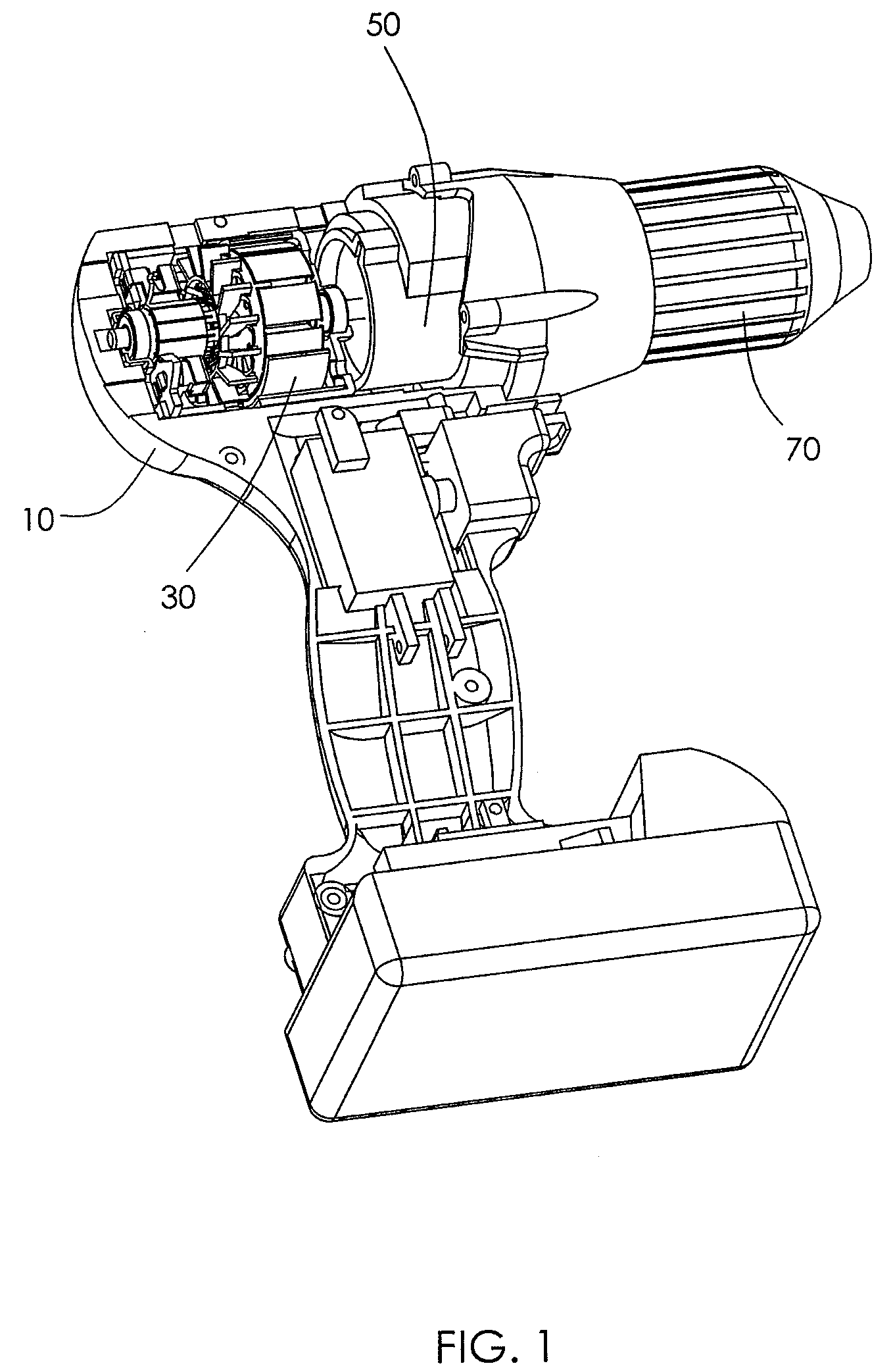
[0027]It should be understood that the power tool according to the present invention could be a drill, hammer, saw, planer, impact wrench, spanner or the like. To simplify the description, various embodiments of the present invention will be described using a portable, hand held, cordless, power drill as an example.

[0028]FIG. 1 illustrates a portable cordless drill with a portion of the casing cut away to show some of the parts inside. The drill comprises a housing 10, a motor 30 arranged in the housing 10, a speed reduction mechanism 50 in the form of a planetry gearbox, coupled to the shaft of the motor 30, and a drilling head or chuck 70 driven by the speed reduction mechanism 50.

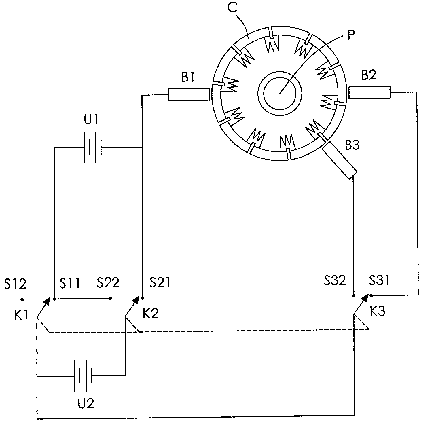
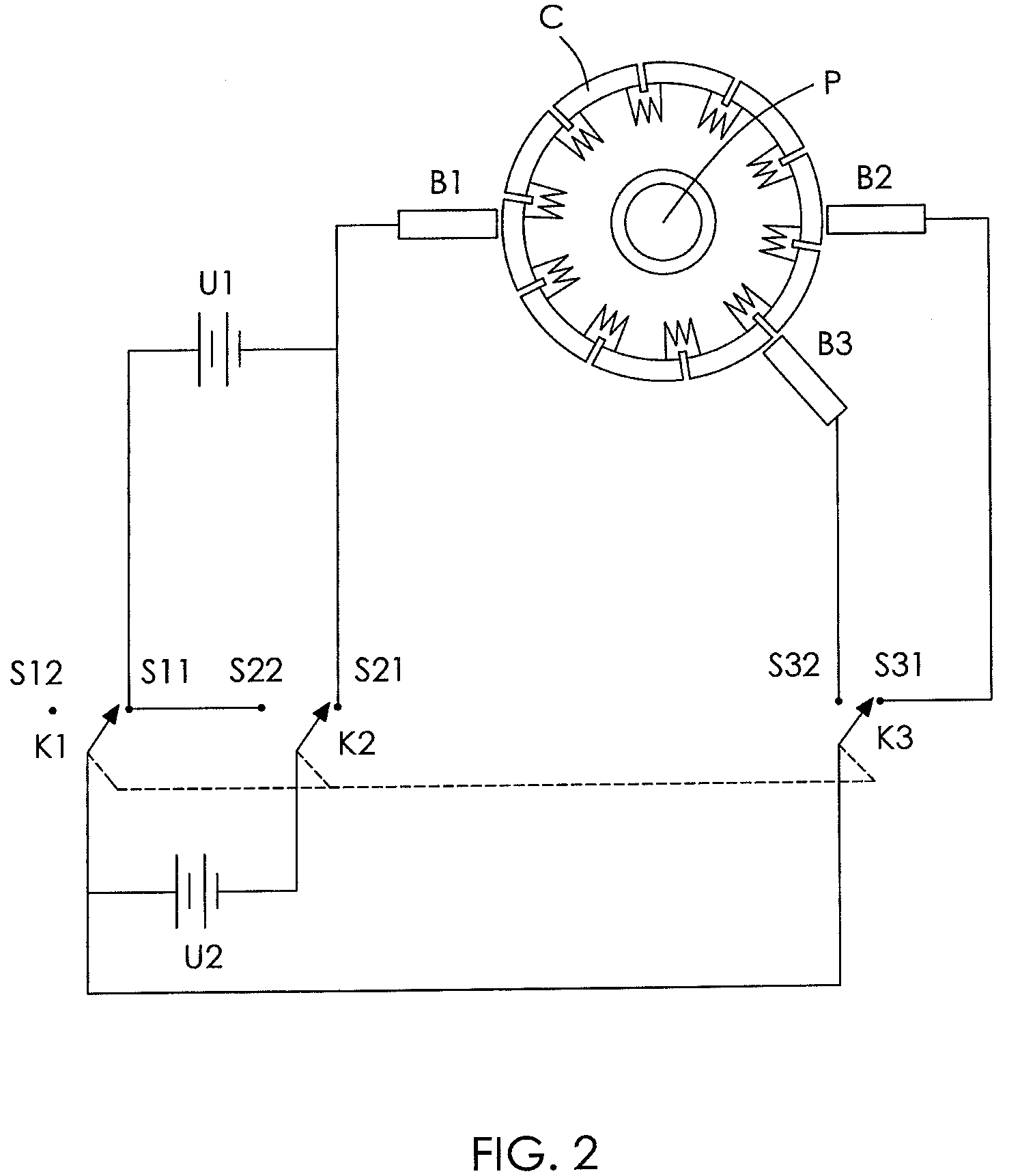
[0029]FIG. 2 schematically illustrates a direct current (DC) motor comprising a commutator C, a common brush B1, a low speed brush B2, a high speed brush B3, two DC power sources U1, U2, and a switching device. The brushes B1, B2, B3 are in sliding contact with the commutator C. The commutator C is attac...


PUM


Abstract

A power tool comprises a housing, a direct current motor arranged in the housing, a speed reduction mechanism coupled to a shaft of the motor, a tool head driven by the speed reduction mechanism, a first direct current power source, and a switching device. The motor comprises a common brush, a high speed brush and a low speed brush which are in sliding contact with a commutator. The switching device is configured to selectively connect the common brush and the high speed brush with the power source to operate the motor in a high speed mode and to connect the common brush and the low speed brush with the power source to operate the motor in a low speed mode.

Description

CROSS REFERENCE TO RELATED APPLICATIONS[0001]This non-provisional patent application claims priority under 35 U.S.C. §119(a) from Patent Application No. 200910108907.9 filed in The People's Republic of China on Jul. 17, 2009 and from Patent Application No. 200910108831.X filed in The People's Republic of China on Jul. 23, 2009.FIELD OF THE INVENTION[0002]This invention relates to a power tool and in particular, to a power tool having a multi-speed DC motor.BACKGROUND OF THE INVENTION[0003]Power tools are often required to operate in different speed modes. For example, when a drill driven by a motor is used for drilling holes, high speed operation is required, and when it is used for turning screws, low speed operation is required. Speed control is commonly provided by a speed reduction mechanism such as a planetry gearbox. Multiple stages are provided in the gearbox to achieve the desired maximum speed and minimum speeds. However, adding stages to the gearbox is costly in terms of m...

Claims


Application Information

Patent Timeline
Patent Type & Authority Patents(United States)
IPC IPC(8): H01R39/42H02P3/00H02P1/16H02K13/00H01R39/44
CPCH02P7/08H02K7/145H02K13/10H02K23/20H02K23/66
Inventor LAU, JAMES CHING SIKJIN, CHANG LIN
Owner JOHNSON ELECTRIC SA
Why Eureka
Try Eureka