

Motor drive system and process
a technology of motor drive and process, which is applied in the direction of dynamo-electric converter control, multiple dynamo-motor starters, electric devices, etc., can solve the problems of increasing the size of the system, the manufacturing cost, and the tendency of the dc converter to use, so as to increase the size of the system, the manufacturing cost, and the effect of loss
- Summary
- Abstract
- Description
- Claims
- Application Information
AI Technical Summary
Benefits of technology
Problems solved by technology
Method used
Image

Examples
1st embodiment
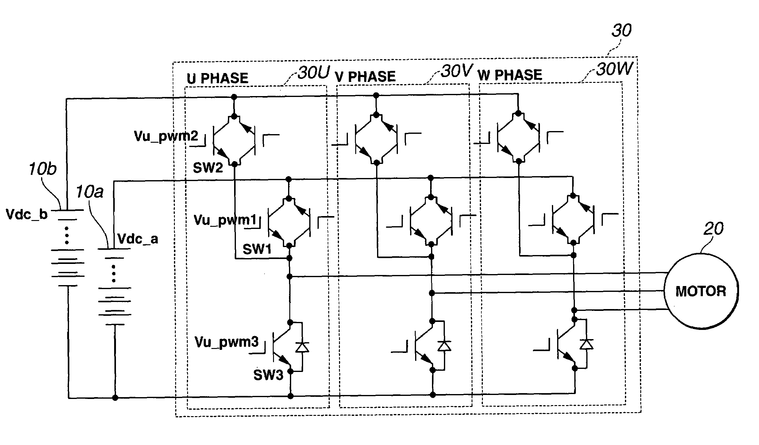
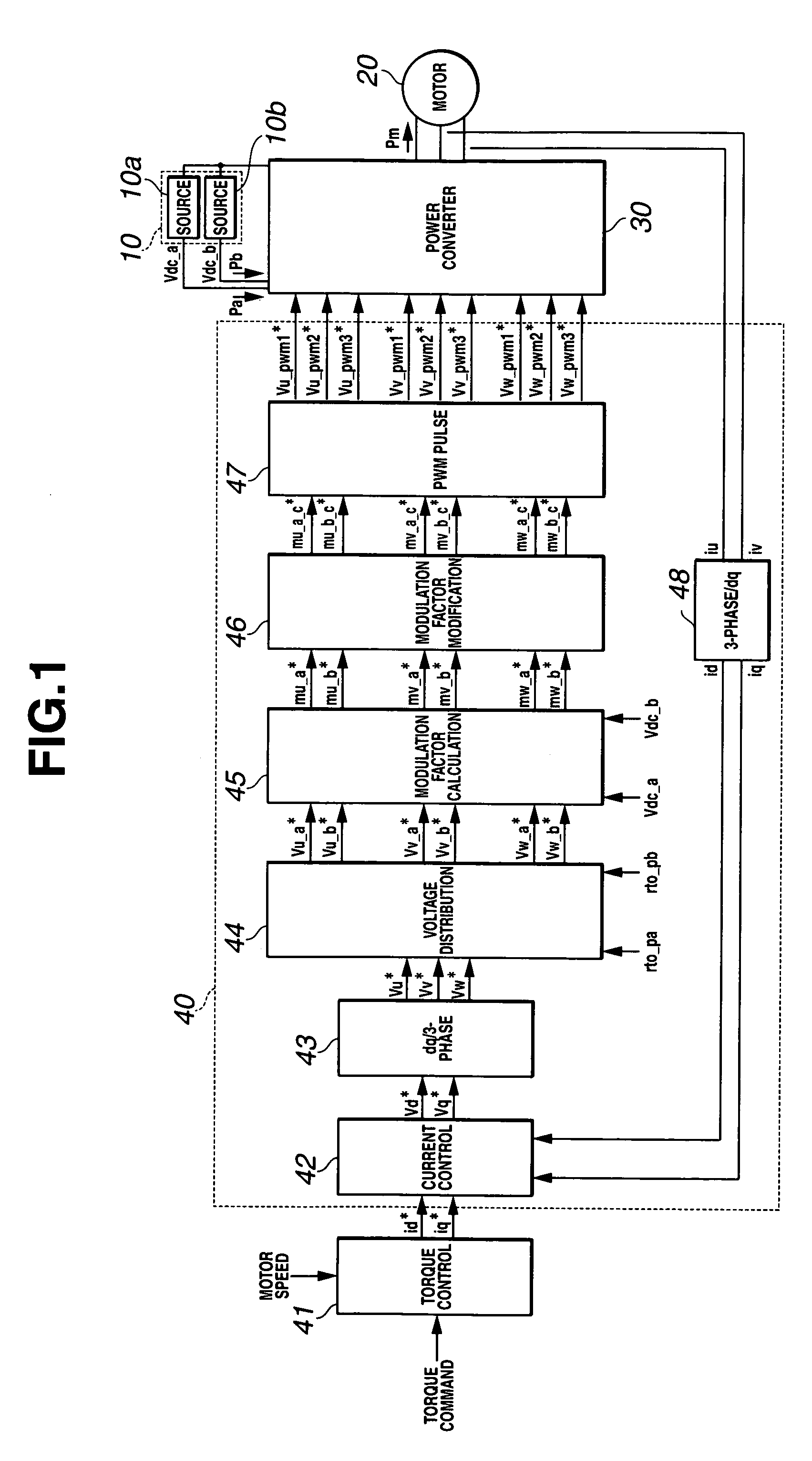
[0047]FIG. 1 shows, in the form of a functional block diagram, a motor drive system according to a first embodiment of the present invention. The motor drive system is a control system for controlling a motor. The motor drive system of FIG. 1 includes a multi-output dc power source 10 including a first dc power source (first dc voltage supplying section) 10a and a second dc power source (second dc voltage supplying section) 10b; a motor 20; a power converter 30 for producing a voltage to be applied to motor 20 by using voltages of this multi-output power source 10; and a control unit (or controller) 40 for controlling a torque of motor 20 by driving power converter 30, and controlling a power distribution ratio between first and second power sources 10a and 10b.
[0048]In multi-output power source 10, the lower potential terminals (or electrodes) of first and second dc power sources 10a and 10b are connected together to a common terminal providing a common potential (GND potential). ...
2nd embodiment
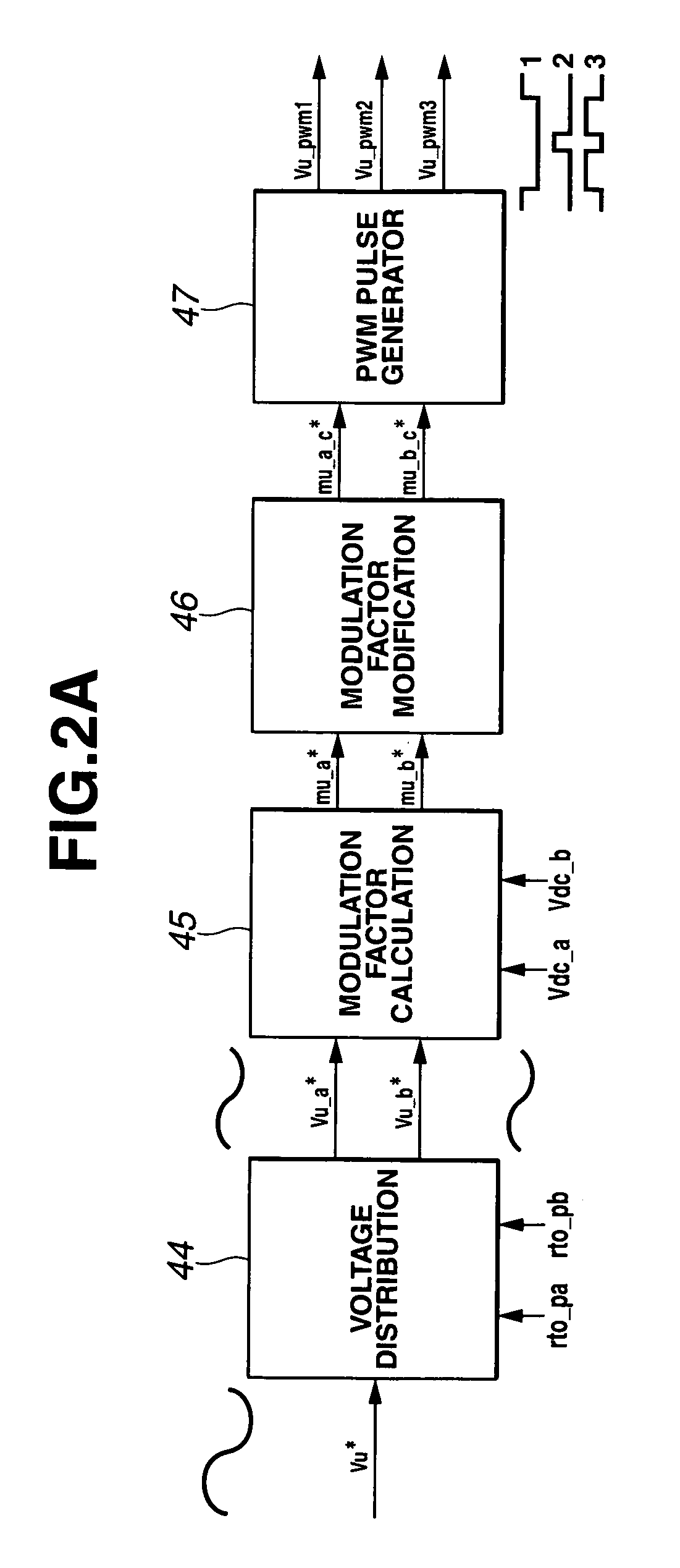
[0065]FIG. 2B is a functional block diagram showing part of control unit 40 according to a second embodiment, and FIG. 5B is a timing chart for illustrating the PWM pulse generating method in the second embodiment. The control unit shown in FIG. 2B of the second embodiment is different from that of FIG. 2A of the first embodiment in a PWM pulse generating section 47a. The calculation 4 shown in the fourth step of FIG. 4 is different from that of the first embodiment, in the following manner.
[0066]FIG. 5B is a view for illustrating operations of PWM pulse generating section 47a. First carrier shown in FIG. 5B is a sawtooth carrier for generating PWM pulses to produce voltage pulses from the voltage Vdc_a of first power source 10a; and second carrier is a sawtooth carrier for generating PWM pulses to produce voltage pulses from the voltage Vdc_b of second power source 10b, to drive the switches. The first and second sawtooth carriers linearly rise and fall alternately between an upper...
3rd embodiment
[0069]FIG. 14 is a functional block diagram showing a motor drive system according to a third embodiment. The motor drive system according to the third embodiment is different from that of the first embodiment in a modulation factor modifying section 46a. In the other respects, the motor drive system of the third embodiment is substantially identical to the motor drive system of the first embodiment. In the first embodiment, the first time Tp1 allotted to a pulse produced on the basis of the first modified command modulation factor mu_a_c* for first power source 10a is equal to the second time Tp2 allotted to a pulse produced on the basis of the second modified command modulation factor mu_b_c* for second power source 10b, and Tp1=Tp2=Tpwm / 2. In the third embodiment, by contrast, the motor control system is configured to vary the first time (interval) Tp1 and second time (interval) Tp2 in accordance with the voltage distribution commands rto_pa and rto_pb, so as to utilize the dc so...
PUM
 Abstract
Description
Claims
Application Information