
Wireless module with integrated antenna by using rigid-flex board

a wireless module and rigid-flex board technology, applied in the direction of antennas, antenna details, basic electric elements, etc., can solve the problems of significant increase in component cost, design is not suitable for use in a small-sized electronic product, and the antenna location optimization is not facilitated, so as to achieve reliable signal quality and reduce loss and cost

Active Publication Date: 2015-04-30
UNIVERSAL SCIENTIFIC INDUSTRIAL (SHANGHAI) CO LTD +1
View PDF6 Cites 10 Cited by
  • Summary
  • Abstract
  • Description
  • Claims
  • Application Information

AI Technical Summary

Benefits of technology

The present invention provides a wireless module with an integrated antenna using a rigid-flex board to reduce signal loss and costs. The signal layer and ground layer are continuously arranged on one same flex substrate to improve signal transmission performance and quality, and reduce component costs. The flex substrate facilitates optimization of the antenna and reduces the size of the wireless module for easy installation. The communication unit is packaged on the rigid substrate using the SiP technique for easier application.

Problems solved by technology

This design has the drawback of large size, not facilitating locational optimization of the antenna.
Therefore, this design is not suitable for use in a small-sized electronic product.
However, according to this design, the RF connector and the cable must use special materials and design techniques , to reduce high-frequency loss, resulting in significant increase in component costs.
A pin connector can be used to substitute for the aforesaid RF connector and cable for high-frequency loss reduction, however the impedance. matching problem in signal transmission greatly increase the degree of design difficult
However, because the power layer and the ground layer are interruptedly mounted in the rigid PC board and a flex PC board, this design not only increases circuit complexity, but also may introduce unnecessary noises.

Method used


Image

  • Wireless module with integrated antenna by using rigid-flex board
  • Wireless module with integrated antenna by using rigid-flex board
  • Wireless module with integrated antenna by using rigid-flex board

Examples


Embodiment Construction

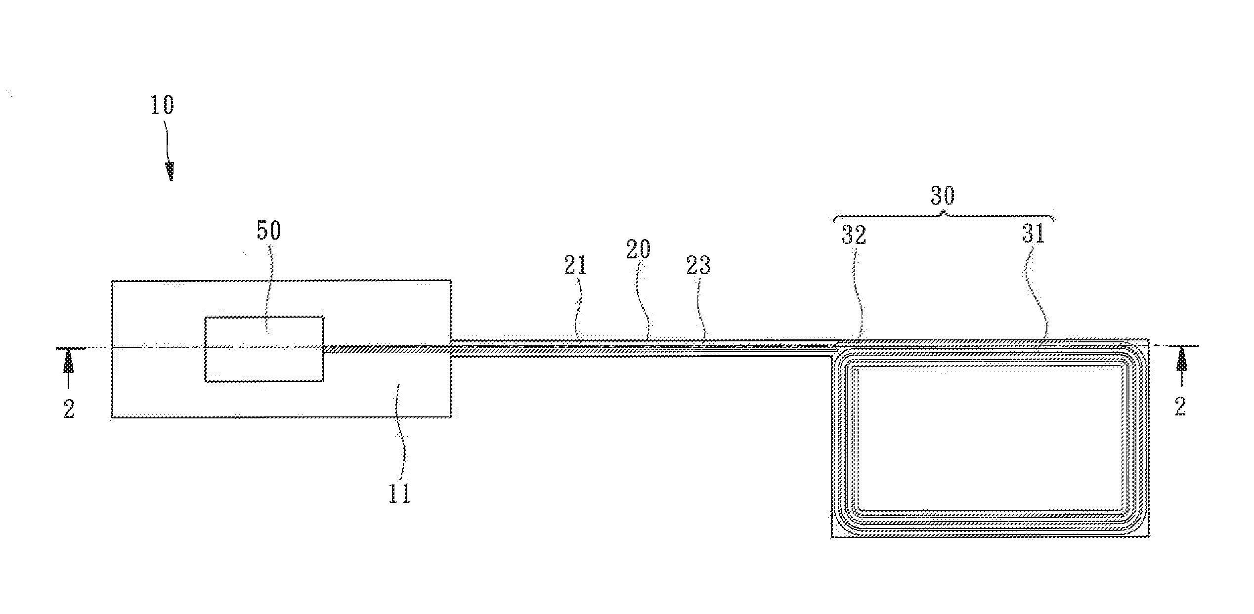
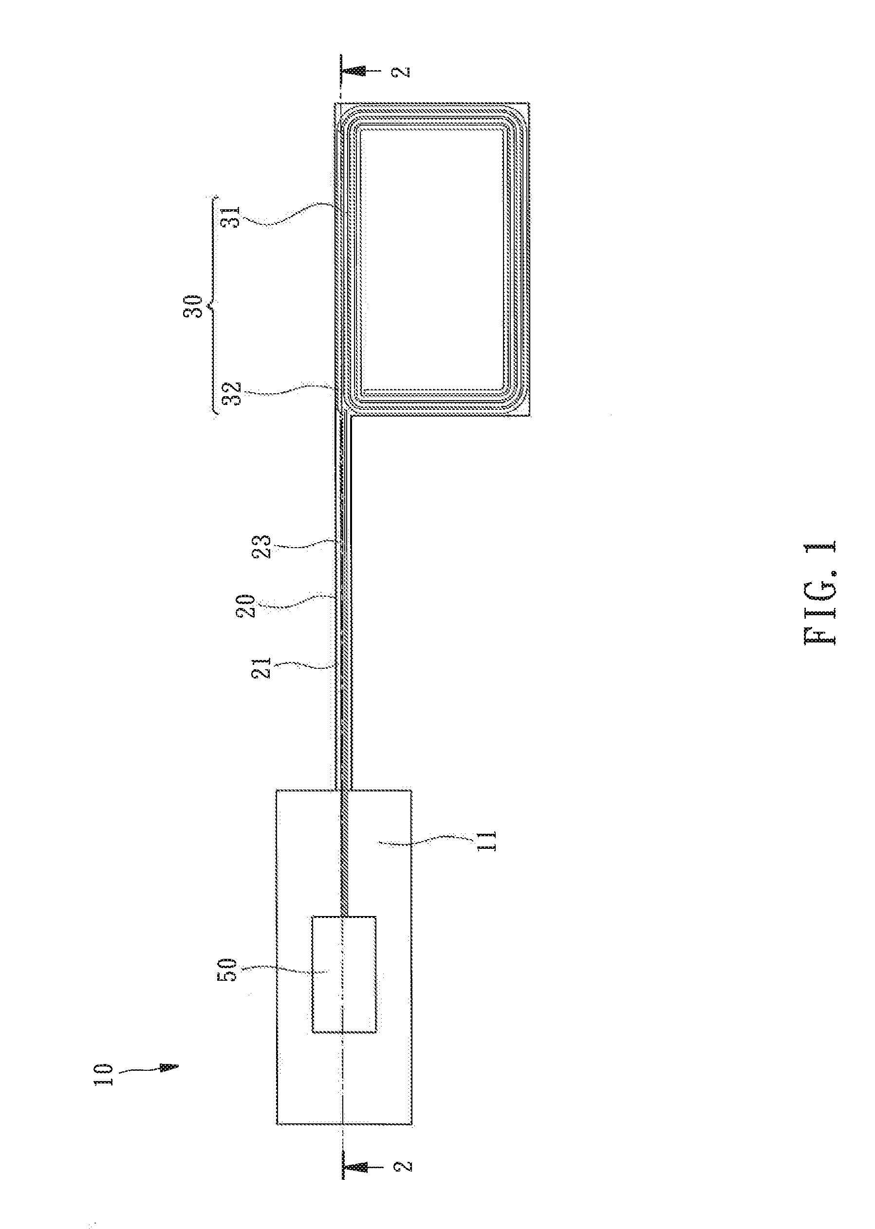
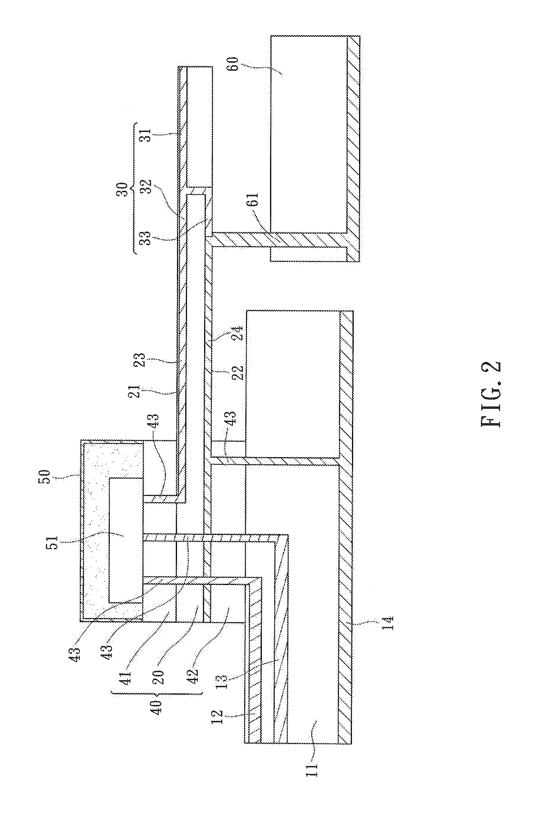
[0015]Referring to FIGS. 1 and 2, a wireless module 10 in accordance with the present invention is shown. The wireless module 10 comprises a flex substrate 20, an antenna 30 integrated in one side of the flex substrate 20, two rigid substrates 41 and 42 stacked on an opposite side of the flex substrate 20 remote from the antenna 30, and a communication unit 50 integrated in the rigid substrate 41. The structural features of the aforesaid components are outlined hereinafter.

[0016]The flex substrate 20 comprises a first surface 21, a second surface 22 opposite to the first surface 21, an electrically conducting signal layer 23 integrated n the first surface 21, and an electrically conducting ground layer 24 integrated in the second surface 22.

[0017]The antenna 30 is integrated in the first surface 21 of the flex substrate 20. In this embodiment, the antenna 20 is a NFC (Near Field Communication) antenna, comprising a radiator 31, and a feed-in segment 32 and a grounding segment 33 ext...


PUM


Abstract

A wireless module includes a flex substrate, an antenna integrated in the flex substrate and electrically connected to a signal layer and a ground layer of the flex substrate, a first rigid substrate stacked on one side of the flex substrate remote from the antenna, and a communication unit mounted on the first rigid substrate and electrically connected to the signal layer. Thus, the flex substrate and the first rigid substrate are laminated into a Rigid-Flex board. Further, the signal layer and the ground layer are continuously arranged in the same flex substrate, It will be helpful in decreasing the uncertainty and loss of RF signal transmission path, reducing component costs, facilitating optimization of the antenna and reducing the module size.

Description

BACKGROUND OF THE INVENTION[0001]1. Field of the Invention[0002]The present invention relates to a built-in wireless module for handheld electronic device and more particularly, to a wireless module with integrated antenna by using rigid-flex board having the characteristics of small size, low loss, low cost, and design and optimization facilitation.[0003]2. Description of the Related Art[0004]With new advances in technology, all kinds of handheld electronic products are used widely and developed with the tread toward deeper integration and smaller handheld sizes. In consequence, built-in electronic communication module is inevitably developed towards the same trend.[0005]Conventional wireless module designs commonly have the communication IC and the antenna be mounted in one single printed circuit board. This design has the drawback of large size, not facilitating locational optimization of the antenna. Therefore, this design is not suitable for use in a small-sized electronic prod...

Claims


Application Information

Patent Timeline
IPC IPC(8): H01Q1/38H01Q1/22
CPCH01Q1/2208H01Q1/38H01Q23/00
Inventor CHEN, HSIN-HONGSHIH, RUEI-KUNLIU, E-CHAN
Owner UNIVERSAL SCIENTIFIC INDUSTRIAL (SHANGHAI) CO LTD
Learn More