Reducing gas generator and solid reductant SCR system having the generator

a gas generator and reductant technology, applied in the direction of liquid chemical processes, lighting and heating apparatus, separation processes, etc., can solve the problems of low volumetric efficiency, difficulty in practical realization of the scr system that treats exhaust gas discharged, for example, from a small-scale automotive engine, and freeze-up of aqueous solution in a low-temperature environment, so as to reduce the gas generator and reduce the cost. , the effect of simplifying the configuration

Active Publication Date: 2008-10-23
DENSO CORP
View PDF6 Cites 36 Cited by
  • Summary
  • Abstract
  • Description
  • Claims
  • Application Information

AI Technical Summary

Benefits of technology

[0010]The present invention addresses the above disadvantages. Thus, it is an objective of the present invention to provide a reducing gas generator, which has a simplified configuration using a solid reductant having high volumetric efficiency to accurately control generation of reducing gas, and an SCR system having the generator.

Problems solved by technology

However, when the above aqueous solutions are used, their volumetric efficiency is low.
Ammonia that is used effectively for exhaust treatment corresponds to about 30 percent of the volume of the aqueous solution, since solubility of ammonia or urea is limited.
Thus, a large amount of aqueous solution is difficult to install in a limited space of the vehicle, and consequently practical realization of the SCR system that treats exhaust gas discharged, for example, from a small-scale automotive engine, is hindered.
In addition, there is concern about aqueous solution freeze-up in a low-temperature environment, block in pipes with crystals precipitated out of the aqueous solution, and corroded pipes due to a corrosive aqueous solution.
Therefore, a reducing gas generator using the solid reductant in the conventional SCR system has a complex structure, and the generation amount of the gaseous reductant 207 is difficult to stabilize.

Method used


Image

  • Reducing gas generator and solid reductant SCR system having the generator
  • Reducing gas generator and solid reductant SCR system having the generator
  • Reducing gas generator and solid reductant SCR system having the generator

Examples


first embodiment

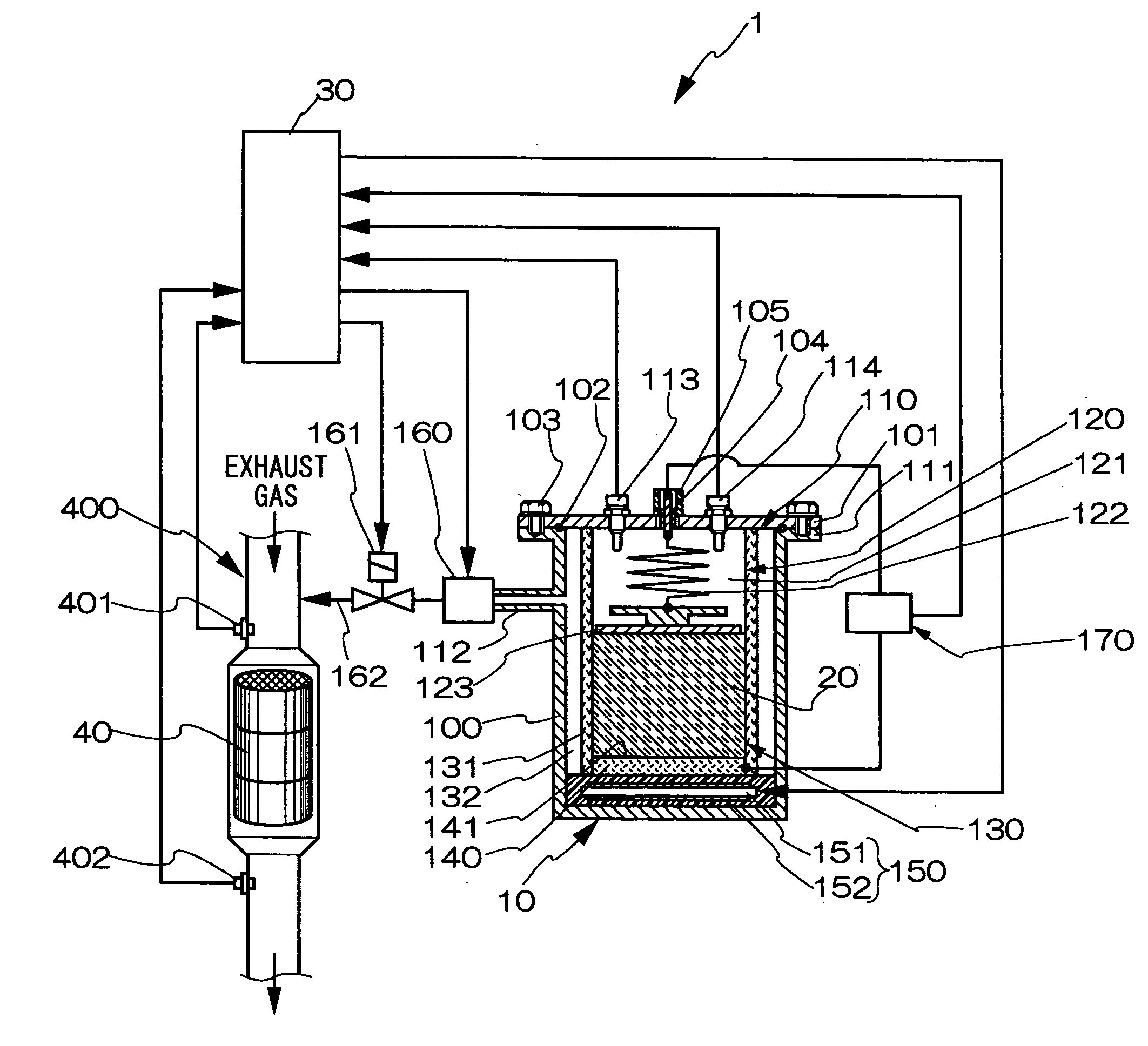
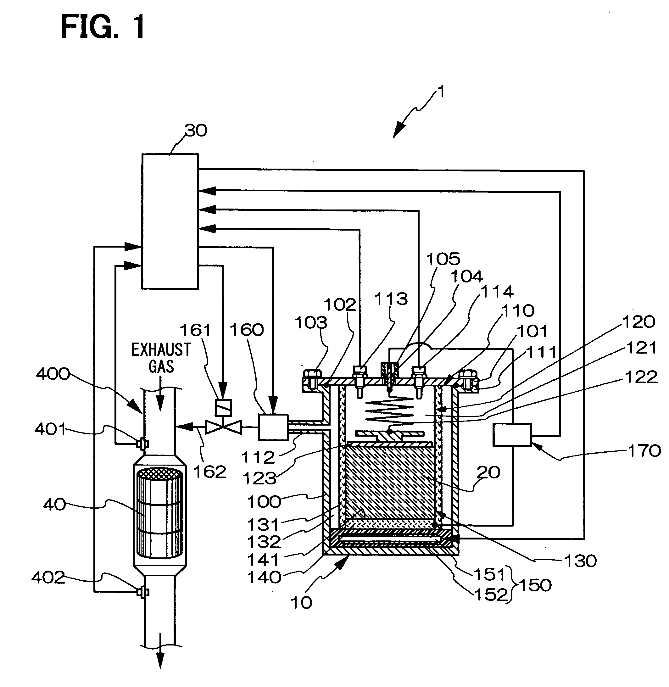
[0042]A specific configuration of the reducing gas generator 10 according to the invention is described in detail with reference to FIGS. 2A, 2B. FIG. 2A is a sectional view of a main part of the reducing gas generator 10 when the heat-generating portion 150 is generating heat. FIG. 2B is a cross-sectional view taken along a line IIB-IIB in FIG. 2A. In FIGS. 2A, 2B, a flow of the reducing gas 21, which is generated from the solid reductant 20, is indicated by an arrow. The container 100 covers the solid reductant receiving portion 130 and the heat-generating portion 150. The container 100 is formed in a based cylindrical shape with its upper end portion opened and its lower end portion blocked. The container 100 is formed in a hat-like shape having a flanged portion 111 projecting outward around an outer circumferential portion at its upper end. A container cover 101 is formed in a flat plate-like shape and covers an opening 110 of the container 100. The container cover 101 is air-t...

second embodiment

[0055]As shown in FIGS. 5A, 5B, a specific ventilation means in a reducing gas generator 10a according to the invention may include a bottom wall groove portion 142, a side wall groove portion 133, and a side surface opening 134. The bottom wall groove portion 142 has at least a single groove formed on an inside surface 141a of a solid reductant receiving portion bottom wall 140a in a radially outward direction from the center of the inside surface 141a. The side wall groove portion 133 has at least a single groove communicating with the bottom wall groove portion 142 and formed on an inner circumferential surface of a solid reductant receiving portion side wall 131a in a direction from its lower to upper end. The side surface opening 134 is formed at an upper portion of a solid reductant receiving portion 130a and connected to the side wall groove portion 133. Accordingly, the inside and outside of the solid reductant receiving portion side wall 131a communicate through the side su...


PUM

PropertyMeasurementUnit
heataaaaaaaaaa
cylindrical shapeaaaaaaaaaa
heat-generatingaaaaaaaaaa

Abstract

A reducing gas generator generates reducing gas including ammonia. The generator includes a solid reductant and a heat-generating portion. The solid reductant is formed in a columnar shape. A cross-sectional surface of the solid reductant has a constant shape and is perpendicular to a central axis of the solid reductant. The heat-generating portion includes a heat-generating surface opposed to a lower surface of the solid reductant in a vertical direction thereof and in contact with an entire region of the lower surface, and a heating element that heats the heat-generating surface when energized, so that the solid reductant is heated and decomposed to generate the reducing gas.

Description

CROSS REFERENCE TO RELATED APPLICATION[0001]This application is based on and incorporates herein by reference Japanese Patent Application No. 2007-113439 filed on Apr. 23, 2007.BACKGROUND OF THE INVENTION[0002]1. Field of the Invention[0003]The present invention relates to a reducing gas generator using a solid reductant as a generation source of reducing gas such as ammonia that reduces nitrogen oxide in exhaust gas and to a solid reductant SCR system having the reducing gas generator.[0004]2. Description of Related Art[0005]An SCR (selective catalytic reduction) system is of use in a whole range of fields as a means for removing nitrogen oxide in exhaust gas. In the SCR system, nitrogen oxide in exhaust gas reacts selectively with reducing gas such as ammonia by catalysis and is thereby reduced to harmless nitrogen. When nitrogen oxide in exhaust gas discharged from a large-scale plant such as a thermal power plant is treated, ammonia stored in a high-pressure tank is directly con...

Claims


Application Information

Patent Timeline
Patent Type & Authority Applications(United States)
IPC IPC(8): C01C1/00
CPCB01B1/005B01D7/00C01C1/086B01D2257/404C01C1/026B01D2251/2067
Inventor SUZUKI, KAZUNORIKUROYANAGI, MASATOSHINISHIJIMA, YOSHIAKI
Owner DENSO CORP
Why Eureka
Try Eureka