Medical suspension device comprising an offset arm

a suspension device and offset arm technology, applied in the field of suspension devices, can solve the problems of creating singularities over the use zone, causing collisions between stationary or moving equipment, and various equipment items can drift, so as to reduce the number of anchor points, reduce and solve the problem of increasing the number of rotary objects

Active Publication Date: 2019-10-22
MAQUET SAS
View PDF24 Cites 0 Cited by
  • Summary
  • Abstract
  • Description
  • Claims
  • Application Information

AI Technical Summary

Benefits of technology

[0014]With this arrangement, it is possible to create artificial offsetting of the items of equipment carried by the distribution arms (the suspension arm and the spring arm) from centralized anchoring in order to obtain a 9 o'clock 3 o'clock type configuration that is known to limit the collisions and the number of singular positions in the zone of use, while also being compatible with the laminar flows of an operating theater having centralized anchoring.
[0015]Such artificial offsetting is an inexpensive and quick solution for changing the arrangement of the items of equipment in the operating theater around the zone of use because it is compatible with an existing centralized installation, and it makes it possible to reduce the number of anchor points and to reduce the number of rotary and / or pivotal articulations compared with prior art suspension devices.

Problems solved by technology

It is understood by medical staff that, during an operation, moving the articulated arms carrying the various items of equipment can give rise to collisions between stationary or moving items of equipment.
In addition, even though medical staff are often satisfied with the main function of such suspension devices, they often complain about positioning difficulties, and needing to apply large forces to manipulate the suspension devices, and they also mention that the various items of equipment can drift.
Another complaint made by medical staff concerns positions for items of equipment, such as lighting devices, that are impossible to reach over the zone of use, thereby creating singularities over the zone of use.
Nevertheless, operating theaters are not always compatible for such installations that require a plurality of anchor points, conventional theaters making it possible for anchoring of a suspension device to be central only.

Method used


Image

  • Medical suspension device comprising an offset arm
  • Medical suspension device comprising an offset arm

Examples


Embodiment Construction

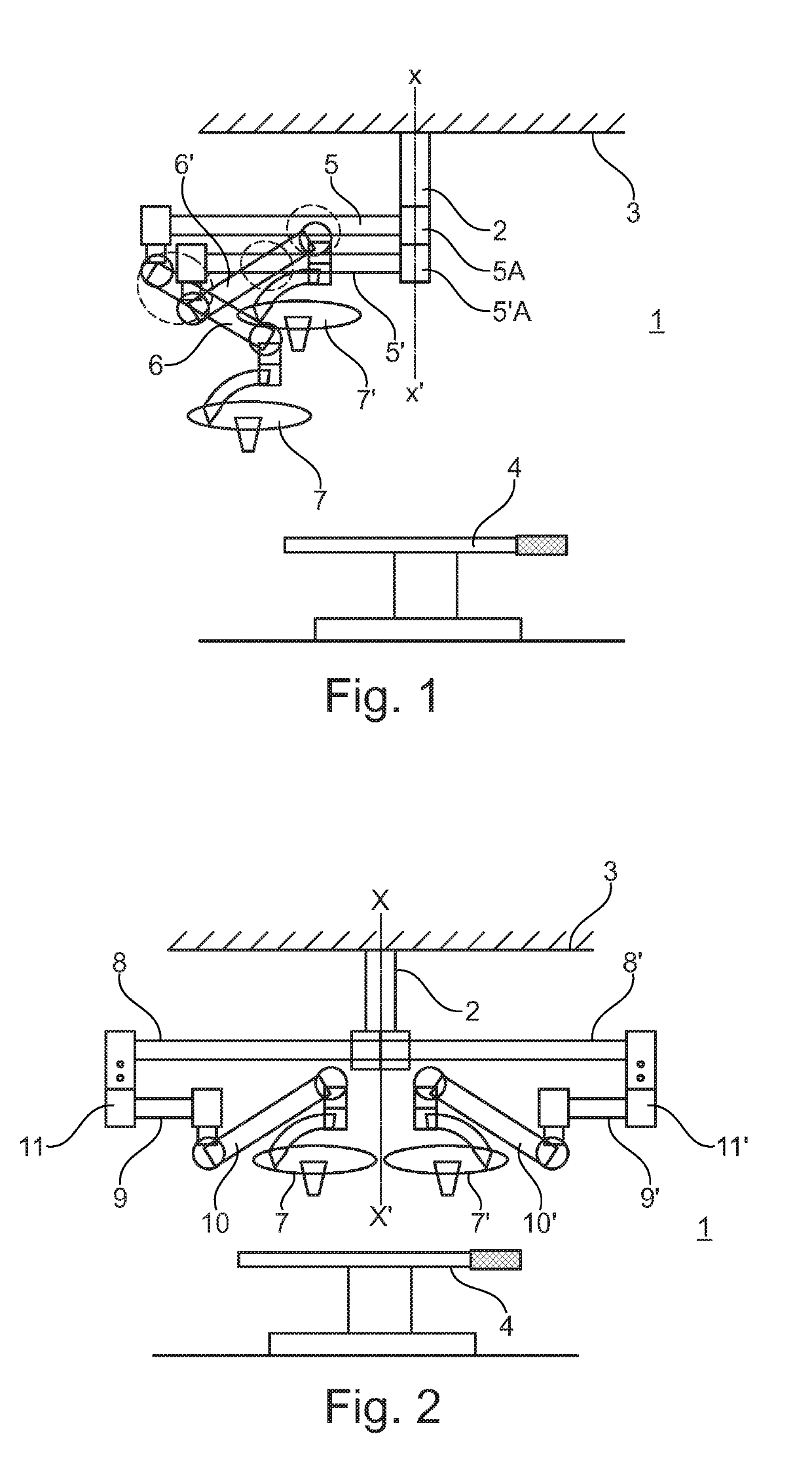
[0022]FIG. 1 shows a prior art suspension device in an operating theater 1 with an anchor bracket 2 anchored to a support structure 3 or ceiling of the operating theater, above an operating table 4.

[0023]During a medical operation, the medical staff usually align the center of the operating table 4 so that it is vertically in register with the anchor bracket 2.

[0024]FIG. 1 shows two adjustable distribution arms, each of which is articulated relative to the anchor bracket 2, and each of which carries medical equipment 7, 7′, namely medical lighting in this example, at its free end.

[0025]Instead of medical lighting 7, 7′, any other electronic system could be carried, e.g. a monitoring and control system including a screen and a camera. The equipment could also be a fluid dispensing system, e.g. an intravenous drip, etc.

[0026]Conventionally, each distribution arm comprises a suspension arm 5, 5′ connected at one end to the anchor bracket 2 via a pivot articulation 5A, 5′A and at the ot...


PUM


Abstract

A suspension device making it possible to suspend items of equipment (7, 7′) under a support structure comprises an anchor bracket (2) designed to be anchored axially to the support structure, two distribution arms (9, 10, 9′, 10′) that are adjustable up and down and that are designed to carry the items of equipment (7, 7′), and that are connected to the anchor bracket (2) via pivot articulations (11, 11′), each of which is offset from the anchor bracket (2) via a stationary offsetting arm (8, 8′; 8″).

Description

CROSS REFERENCE TO RELATED APPLICATIONS[0001]This application is the U.S. National Stage of International Application Number PCT / FR2017 / 050102 filed on Jan. 18, 2017, which application claims priority under 35 USC § 119 to French Patent Application No. 1650394 filed on Jan. 19, 2016. Both applications are hereby incorporated by reference in their entirety.TECHNICAL FIELD[0002]The field of the invention relates to a suspension device making it possible to suspend items of equipment under a support structure, such a suspension device comprising an anchor bracket designed to be anchored axially to the support structure, two distribution arms that are adjustable up and down and that are designed to carry the items of equipment, each distribution arm comprising a suspension arm having one end articulated to the anchor bracket via a pivot articulation making it possible for the suspension arm to move in rotation in a horizontal plane, and a spring arm articulated to the other end of the s...

Claims


Application Information

Patent Timeline
Patent Type & Authority Patents(United States)
IPC IPC(8): F16M13/02F16M11/24F16M11/20A61G12/00A61B90/35A61B90/50
CPCF16M11/2092A61B90/50F16M13/027A61G12/004A61B90/35F16M11/2014F16M11/24F16M2200/063
Inventor RAVALITERA, PIERREGUILLEMINOT, BERTRANDSENELIER, GREGORY
Owner MAQUET SAS
Why Eureka
Try Eureka