Unlock instant, AI-driven research and patent intelligence for your innovation.

Golf simulator, and golf simulation method

a golf simulator and golf technology, applied in the field of simulation systems, can solve the problems of large spin error and negative opinion of golfers, and achieve the effect of reducing unnecessary resources and efforts for image analysis, accurate golf ball spin rate, and accurate calculation of golf ball spin

Active Publication Date: 2019-10-29
RD TEK CO LTD
View PDF25 Cites 0 Cited by
  • Summary
  • Abstract
  • Description
  • Claims
  • Application Information

AI Technical Summary

Benefits of technology

[0013]According to the present invention, a relatively more accurate spin rate of a golf ball is calculated using a separate image compared with using an output of an optical sensor, and the calculated spin rate is combined with data measured by the optical sensor to accurately calculate a golf ball spin as well as a velocity and direction of the golf ball, thereby capable of simulating a flying trajectory of the golf ball, which is more proximate to reality.
[0014]In addition, since only images required to calculate the spin rate are input, unnecessary resources and efforts for image analysis can be reduced.
[0015]In addition, an optimal operation environment can be set according to an installation or operation environment of the simulator.
[0016]In addition, a serious error can be excluded which occurs in the spin rate of a golf ball, which is calculated from input images.

Problems solved by technology

Simulation golf rapidly increases users by providing golfers with easier accessibility to a golf game, but there are golfers having negative opinions because a golf simulator does not provide the perfectly same result as an actual game.
At this point, since it is not structurally possible to directly measure a ball spin, a result thereof is mainly estimated using a statistical approach.
However, since a golf ball spin is indirectly measured through calculation or a statistical approach by observing correlations between a club and a ball velocity and direction or the like, there occurs a large error in spin measurement

Method used


Image

  • Golf simulator, and golf simulation method
  • Golf simulator, and golf simulation method
  • Golf simulator, and golf simulation method

Examples


Embodiment Construction

[0024]Hereinafter, it will be described in detail about an exemplary embodiment of the present invention in conjunction with the accompanying drawings.

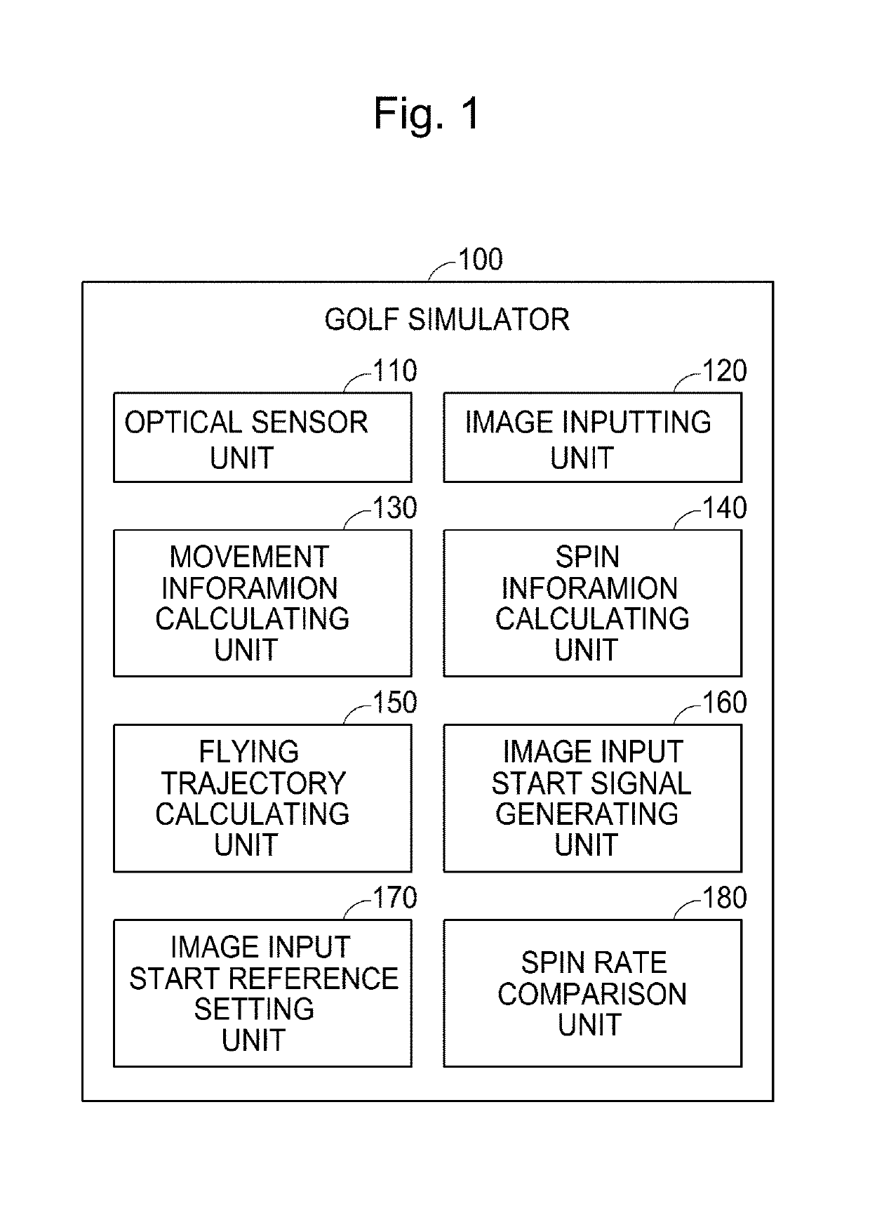
[0025]FIG. 1 is a schematic block diagram of a golf simulator according to an embodiment of the present invention.

[0026]In FIG. 1, a golf simulator 100 includes an optical sensor unit 110, an image inputting unit 120, a movement information calculating unit 130, a spin information calculating unit 140, a flying trajectory calculating unit 150, an image input start signal generating unit 160, an image input start reference setting unit 170, and a spin rate comparison unit 180.

[0027]In FIG. 1, each element of the golf simulator 100 may be implemented only in hardware, but they may be also implemented in software operating with the hardware.

[0028]The optical sensor unit 110 detects a movement path of a golf ball using a plurality of optical sensors. At this point, the optical sensor unit 110 may further detect a movement path of a golf c...


PUM


Abstract

A golf simulator comprises a photosensor unit, an image input unit, a movement information calculation unit, a spin information calculation unit and a flight trajectory calculation unit. The photosensor unit detects a moving path of a golf ball by using a plurality of photosensors, the image input unit inputs movement images of the golf ball, the movement information calculation unit calculates a moving direction and speed of the golf ball from information acquired from the photosensor unit, the spin information calculation unit calculates a spin amount of the golf ball from the inputted images, and the flight trajectory calculation unit calculates a flight trajectory of the golf ball by using movement information and spin information. The speed and direction of a golf ball, and a spin of the golf ball are accurately measured by using a separate image input device to calculate a spin amount of the golf ball.

Description

TECHNICAL FIELD[0001]The present invention relates to a system and method for simulation, and more particularly, to a golf simulating system and a golf simulation method for simulating a golf game.BACKGROUND ART[0002]As golf becomes popular, simulation golf (i.e. screen golf) becomes explosively popular. Simulation golf rapidly increases users by providing golfers with easier accessibility to a golf game, but there are golfers having negative opinions because a golf simulator does not provide the perfectly same result as an actual game.[0003]Currently, a sensor system of a golf simulator senses a golf ball, which is hit by a golfer, with an optical sensor disposed on the bottom, measures a velocity, a direction, and a launch angle of the golf ball, and based on this, estimates a flying trajectory of the golf ball. At this point, since it is not structurally possible to directly measure a ball spin, a result thereof is mainly estimated using a statistical approach.[0004]However, sinc...

Claims


Application Information

Patent Timeline
Patent Type & Authority Patents(United States)
IPC IPC(8): A63B69/36G06K9/00A63B24/00G09B19/00
CPCG06K9/00342A63B69/3658G09B19/0038A63B24/0021A63B2220/806A63B2220/805A63B2220/803A63B2024/0034G06V40/23A63B69/36G01P13/00G01P15/00
Inventor CHOI, SONG HWAN
Owner RD TEK CO LTD