Meter unit and control system with meter unit

a technology of meter unit and control system, which is applied in the direction of program control, instruments, electric programme control, etc., can solve the problems of inability to reliably determine the frequency, the effect of putting a load on the processor system, and the effect of latency and jitter performance of the metering function, so as to achieve fast and accurate metering of quantities or events or frequency determination, the effect of little installation and maintenance complexity

Active Publication Date: 2019-12-10
PHOENIX CONTACT GMBH & CO KG
View PDF15 Cites 3 Cited by
  • Summary
  • Abstract
  • Description
  • Claims
  • Application Information

AI Technical Summary

Benefits of technology

[0004]Therefore, an object of the invention is to provide a fast and accurate metering function having little installation and maintenance complexity.
[0007]The meter unit according to the invention offers many advantages. For example, the meter unit itself can be coupled to a bus system, and a metering function can thus be provided independently from a processor system of a control device. Input data are directly available for the meter module, without detour via the processor system, and result data from the meter module can directly be output onto the bus system, without detour via the processor system. The processor system of the control device can be relieved of the metering function, since the latter can be transferred to the meter unit. This is particularly advantageous if the data throughput otherwise to be managed by the processor system would be very high, due to a metering function for data with high data rates and / or high data volumes. By transferring the metering function to the meter unit, capacity of the processor system is free for other functions, or a cheaper processor system with lower performance may now be used to provide only the remaining control functions. Moreover, since the meter unit is implemented in hardware, it can perform the metering function more rapidly than a processor system that implements the metering function by software. Software-related delays are eliminated, that is, latency and jitter performance of the metering function provided by the meter unit will now meet higher requirements and permit fast and accurate metering of quantities or events or determining of frequencies in reliable manner, even if data are provided at high data rates and / or high data volumes.
[0011]According to a further preferred embodiment, the meter unit comprises a register module adapted to store at least one parameter, wherein the parameter in particular comprises assignment information, a limit value, or a threshold value. In this case, the register module is connected to the control module, and the control module is adapted to control the operation of the meter unit taking into account the parameter stored in the register module. This offers the advantage that the meter unit and the operation thereof can be parameterized and is therefore easily adaptable.
[0012]The control system according to the invention comprises, in addition to a meter unit according to the invention, a control device and a bus system, wherein the meter unit and the control device are connected to the bus system. Thus, the control system also offers the advantages already mentioned.
[0015]According to another preferred embodiment of the control system, the meter unit is coupled to the internal bus or to the external bus. In this case, the bus interface module is appropriately configured for the communication mechanisms and communication protocols of the respective bus. This flexibility of the meter unit in terms of options for connection to different buses is a further advantage.

Problems solved by technology

A drawback of this solution is that input data with information for a meter module originating from a bus subscriber unit and, in the reverse direction, result data from a meter module with information for a bus subscriber unit are always routed via the processor system, and that the meter modules are dependent on the processor system.
On the one hand, this puts a load on the processor system, since the executed software and in particular the application software includes corresponding program steps for querying, processing and forwarding the input data and result data, which program steps must always be executed by the processor system.
On the other hand, the processor system that is always involved and the software that has to be executed by the latter may have an adverse effect on latency and jitter performance of the metering function, so that fast and accurate metering of quantities or events or determining of frequencies is not possible in reliable manner, especially in the case where data are provided at high data rates and / or data volumes.
However, a drawback here is that the meter module has to be arranged remote from the control device and in the vicinity of the respective rotary encoder or sensor, from which it then receives its input signal via a separate line.
Especially in large industrial installations which require a plurality of meter modules, this causes a spatial distribution of the meter modules and requires many separate connection lines and therefore results in increased installation and maintenance complexity.

Method used


Image

  • Meter unit and control system with meter unit
  • Meter unit and control system with meter unit
  • Meter unit and control system with meter unit

Examples


first embodiment

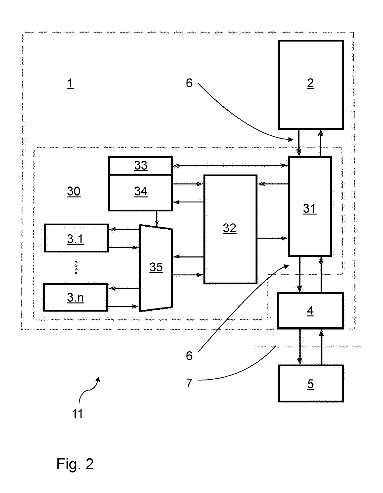
[0043]In contrast to FIGS. 2 and 3, the control system 11 of FIG. 4 comprises a meter unit 30 that is not coupled to the internal bus 6 of control device 1 but to the external bus 7, by means of its bus interface module 31. In this case, bus interface module 31 is appropriately configured for the communication mechanisms and protocols of external bus 7 and in particular functions like a bus interface unit 4 according to FIGS. 2 and 3.

[0044]Thus, meter unit 30 is not comprised in control device 1, but rather itself is coupled to the external bus 7, like control device 1, and is connected to the bus subscriber units 5 via external bus 7. By virtue of the interface unit 4 of control device 1, which couples the internal bus 6 of control device 1 to the external bus 7, meter unit 30 is additionally connected to the processor system 2 of control device 1.

[0045]In this embodiment, again, meter unit 30 receives input data for meter modules 3.1, 3.n originating from processor system 2 and / or...

second embodiment

[0048]In contrast to the second embodiment according to FIG. 4, this control system 11 of FIG. 5 comprises a meter unit 30 which includes a bus interface module 31 and a bus interface unit 4. Bus interface unit 4 connects the meter unit 30 to the external bus 7. Bus interface module 31 and bus interface unit 4 are connected to each other by an internal bus 6. Therefore, bus interface module 31 is appropriately configured for the communication mechanisms and communication protocols of the internal bus 6 of meter unit 30.

third embodiment

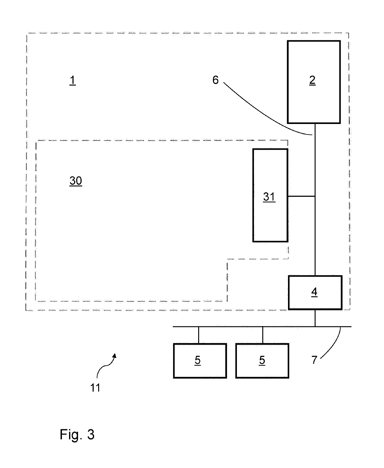
[0049]According to this third embodiment, meter unit 30 is again not comprised in control device 1, but rather itself is coupled to the external bus 7, like control device 1, and is also connected to the bus subscriber units 5 via external bus 7. By virtue of the interface unit 4 of control device 1, which couples the internal bus 6 of control device 1 to the external bus 7, meter unit 30 is moreover connected to the processor system 2 of control device 1.

[0050]In this embodiment, again, meter unit 30 receives input data for meter modules 3.1, 3.n originating from processor system 2 and / or from any one of bus subscriber units 5 via the bus system 6, 7 or from a data stream transferred via the bus system. Furthermore, meter unit 30 outputs result data from meter modules 3.1, 3.n for the processor system 30 and / or for any one of bus subscriber units 5 onto the bus system 6, 7.

[0051]Except for bus interface unit 4 and bus interface module 31, the other modules 32, 33, 34, 35, 3.1, and ...


PUM


Abstract

A meter unit having at least one meter module and a bus interface module, wherein the meter unit is in the form of hardware and the bus interface module can be used to couple the meter unit to a bus system, as a result of which input data for the meter module can be received from a bus system and result data from the meter module can be output onto the bus system. In addition, a control system having such a meter unit is provided, also comprising a control device and a bus system, wherein the meter unit and the control device are connected to the bus system.

Description

FIELD OF THE INVENTION[0001]The invention relates to a meter unit and to a control system comprising such a meter unit for counting quantities, such as a number of items or events, or for determining frequencies.BACKGROUND OF THE INVENTION[0002]In the environment of automated controlled processes it is known to use meters for counting quantities or events and for determining frequencies. For example, FIG. 1 shows a control system known from prior art, in which meter modules in the form of software or hardware function modules are integrated in a processor system of a control device intended for process control, such as a programmable logic controller (PLC), or are directly connected to this processor system. The processor system executes software in the form of firmware and application software, which includes at least one control program. Via an internal bus in the form of a process data bus and a bus interface unit of the control device, the processor system is connected to an ext...

Claims


Application Information

Patent Timeline
Patent Type & Authority Patents(United States)
IPC IPC(8): G06F17/00G05B19/05G06F13/40H04L12/40
CPCH04L12/40G06F13/4072G05B19/05G05B2219/1131
Inventor WITTIG, BERND
Owner PHOENIX CONTACT GMBH & CO KG
Why Eureka
Try Eureka