
Reflector lamp

a technology of reflector lamps and reflectors, which is applied in the direction of reflectors, lighting devices, lighting apparatus, etc., can solve the problems of relatively high installation complexity, relatively expensive reflector lamps overall, and relatively difficult and complex reflector lamps

Inactive Publication Date: 2007-10-18
PATENT TREUHAND GESELLSCHAFT FUR ELECTRIC GLUEHLAMPEN MBH
View PDF2 Cites 6 Cited by
  • Summary
  • Abstract
  • Description
  • Claims
  • Application Information

AI Technical Summary

Benefits of technology

The present invention is a reflector lamp that can be manufactured in a cost-effective manner and with little installation complexity. The reflector and base of the lamp are separate elements that are joined together with a holding device. The reflector and base can be joined without the use of adhesive, making the installation process easier and more simple. The connection region between the reflector and base is designed to absorb torsional forces and prevent relative movement between the reflector and base. The engaging elements and engaging regions in the connection region are complementary, allowing for easy assembly and centering of the reflector and base. The engaging elements and regions can be formed on the reflector or base, and they can be offset inwards or outwards. The connection region can also be in the form of a plug-type connection. Overall, the reflector lamp is designed to be cost-effective, easy to install, and mechanically robust.

Problems solved by technology

However, such reflector lamps are relatively difficult and complex to manufacture.
Furthermore, designs are known in which a glass reflector is assembled with a separate base, which is in the form of ceramic stone, by an unreleasable connection.
However, owing to the cementing of these two components, a higher degree of installation complexity is required.
Owing to this plurality of manufacturing steps, and in particular owing to the additional process of cementing these two elements, a relatively expensive reflector lamp overall results.

Method used


Image

  • Reflector lamp
  • Reflector lamp
  • Reflector lamp

Examples


Embodiment Construction

[0004] The present invention is therefore based on the object of developing a reflector lamp of the generic type such that it can be manufactured in a cost-effective manner and makes little installation complexity possible.

[0005] This object is achieved by a reflector lamp having the features as claimed in patent claim 1.

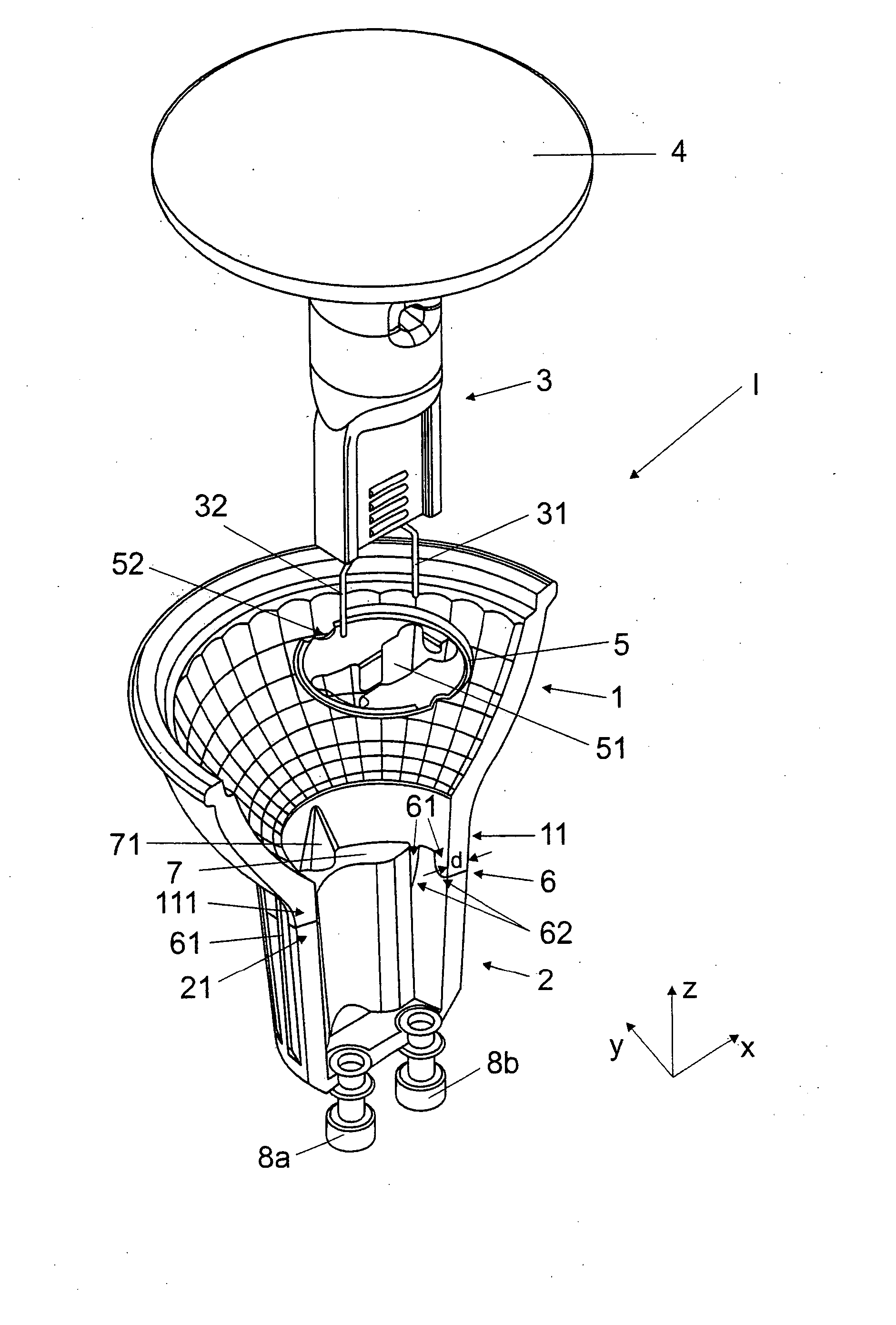
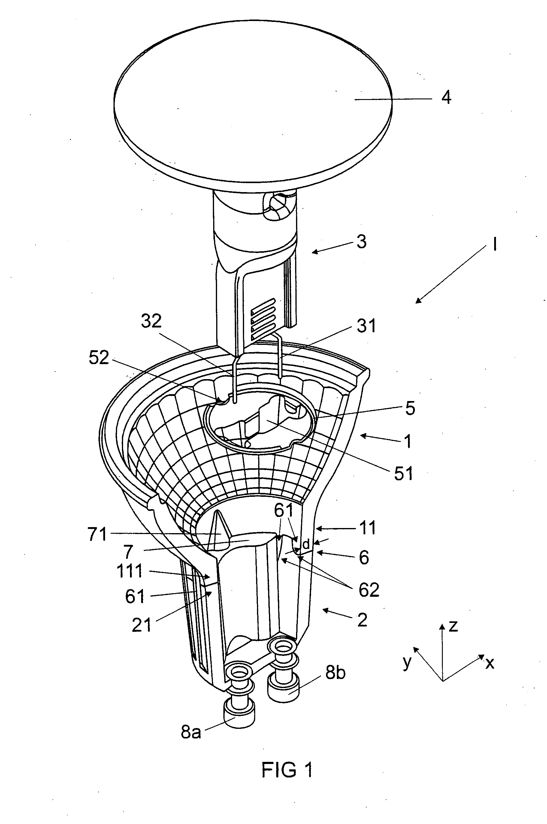
[0006] A reflector lamp according to the invention comprises a reflector and a base, the reflector and the base being formed as separate elements. Furthermore, the reflector lamp has at least one electric lamp, which is held in the reflector and / or the base by means of a holding device. The reflector and the base, in the assembled state of the reflector lamp, are arranged such that they form a common connection region, in which these two components are arranged such that they engage one inside the other, at least in regions, and are assembled or joined without the use of an adhesive.

[0007] As a result, a reflector lamp can be provided which can be manufactured in...


PUM


Abstract

A reflector lamp includes a reflector (1), a separate base (2) and an electric lamp (3), which is held in the reflector (1) and / or the base (2) by a holding device (5), the reflector (1) and the base (2) in the assembled state of the reflector lamp (I) forming a connection region (6), in which they are arranged such that they engage one inside the other, at least in regions, and are assembled without the use of an adhesive.

Description

TECHNICAL FIELD [0001] The invention relates to a reflector lamp having a reflector, a separate base and an electric lamp, which is held in the reflector and / or the base by means of a holding device. PRIOR ART [0002] Reflector lamps, in particular high-volt reflector lamps, are known in which the reflector and the base are designed to be integral and are realized, for example, in the form of all-glass reflectors. For example, such a reflector lamp by the Applicant is known under the name HALOPAR®. One advantage of these all-glass reflectors can be seen in that a relatively small amount of installation complexity is required. However, such reflector lamps are relatively difficult and complex to manufacture. [0003] Furthermore, designs are known in which a glass reflector is assembled with a separate base, which is in the form of ceramic stone, by an unreleasable connection. The glass reflector and the ceramic stone are in this case connected by an adhesive joint, in particular cement...

Claims


Application Information

Patent Timeline
Patent Type & Authority Applications(United States)
IPC IPC(8): F21V7/00
CPCF21V19/0005
Inventor NITTKE, ANDREAS
Owner PATENT TREUHAND GESELLSCHAFT FUR ELECTRIC GLUEHLAMPEN MBH
Learn More