Flat panel display embedding optical imaging sensor

a technology of optical imaging and display screen, which is applied in the direction of planar/plate-like light guides, instruments, mechanical instruments, etc., can solve the problems of limited application of optical fingerprint sensors to various applications such as combining with display devices, and the use of diffused (or diverged) lights having very low directivity, so as to achieve high resolution and sensitivity. , the effect of superiority

Active Publication Date: 2019-12-24
LG DISPLAY CO LTD
View PDF20 Cites 0 Cited by
  • Summary
  • Abstract
  • Description
  • Claims
  • Application Information

AI Technical Summary

Benefits of technology

[0017]In order to overcome the above mentioned drawbacks, a purpose of the present disclosure is to suggest a flat panel display embedding an ultra thin optical image sensor (or an optical image recognition apparatus). Another purpose of the present disclosure is to suggest a flat panel display having an optical image sensor in which most of all or whole surface of the display panel would be used for the sensing area. Still another purpose of the present disclosure is to suggest a flat panel display embedding an optical image sensor in which a directional light is used as a sensing light covering large surface. Yet another purpose of the present disclosure is to suggest a flat panel display embedding an ultra thin and large area optical image sensor of which resolution and sensitivity are very high and / or superior.
[0024]The present disclosure suggests a flat panel display embedding an optical image sensor that has a high resolution recognizing ability or sensitivity by providing the directionized lights (or ‘oriented’) as the sensing lights. Comparing with the diffused lights used in the conventional art for the fingerprint sensor, because that the directionized lights according to the present disclosure are used for sensing the image without any loss of lights so that the present disclosure has the merits of the higher resolution and the superior sensitivity. The present disclosure provides a flat panel display embedding a large area optical image sensor in which a collimated infrared laser beam is expanded over a large area corresponding to the display panel for the sensing lights using a holography technology. The present disclosure provides a flat panel display having an ultra thin optical image sensor in which a direction light is provided on the display surface within a thin thickness. Specifically, as the sensing lights enter perpendicularly into the top surface of the display substrate embedding the image sensors, the light amounts of the sensing lights are not reduced or lowered so that best quality of the image recognition can be acquired. Further, according to the present disclosure, the protective substrate disposed on the topmost surface is used as the cover substrate of the direction optical substrate. Using a holographic film, the collimated light is provided as covering the large area corresponding to the display surface so that the present disclosure suggests an ultra thin direction optical substrate. When joining the optical image sensor to the display device, the whole thickness of the display device is not thicker. As the image sensing area may be set freely within the display area of the display device, the flat panel display embedding an optical image sensor according to the present disclosure may be applied various applications.

Problems solved by technology

There is a limitation to increasing the size of the object for scanning the image.
Therefore, there are limitations for applying the optical fingerprint sensor to various applications such as combining with the display devices.
However, this optical fingerprint sensor uses the diffused (or diverged) lights having very low directivity.
Therefore, there is a limitation to recognize the exact fingerprint pattern.
When using the collimated lights such as the infrared laser having high directivity, it is very hard to generating the sensing lights as covering the wider area.
In order to radiate the collimated lights over the wider scan area, specific scanning structure is required, so that this system is not suitable for portable or personal display apparatus.
However, the capacitive fingerprint sensor also has many problems.
Therefore, the structure would be very complex and further the non-display area (or bezel area) may be increased.
However, the detection ability for the difference of the capacitive storage amount for sensing the fingerprint may be deteriorated by the protective film even though its thickness is very thin.
In that case, the recognition ability may be deteriorated.
When using the collimated lights for enhancing the sensitivity of the optical fingerprint sensor, the bulky and / or complex optical devices are required so that it is very hard to apply to a display for personal mobile device.

Method used


Image

  • Flat panel display embedding optical imaging sensor
  • Flat panel display embedding optical imaging sensor
  • Flat panel display embedding optical imaging sensor

Examples


first embodiment

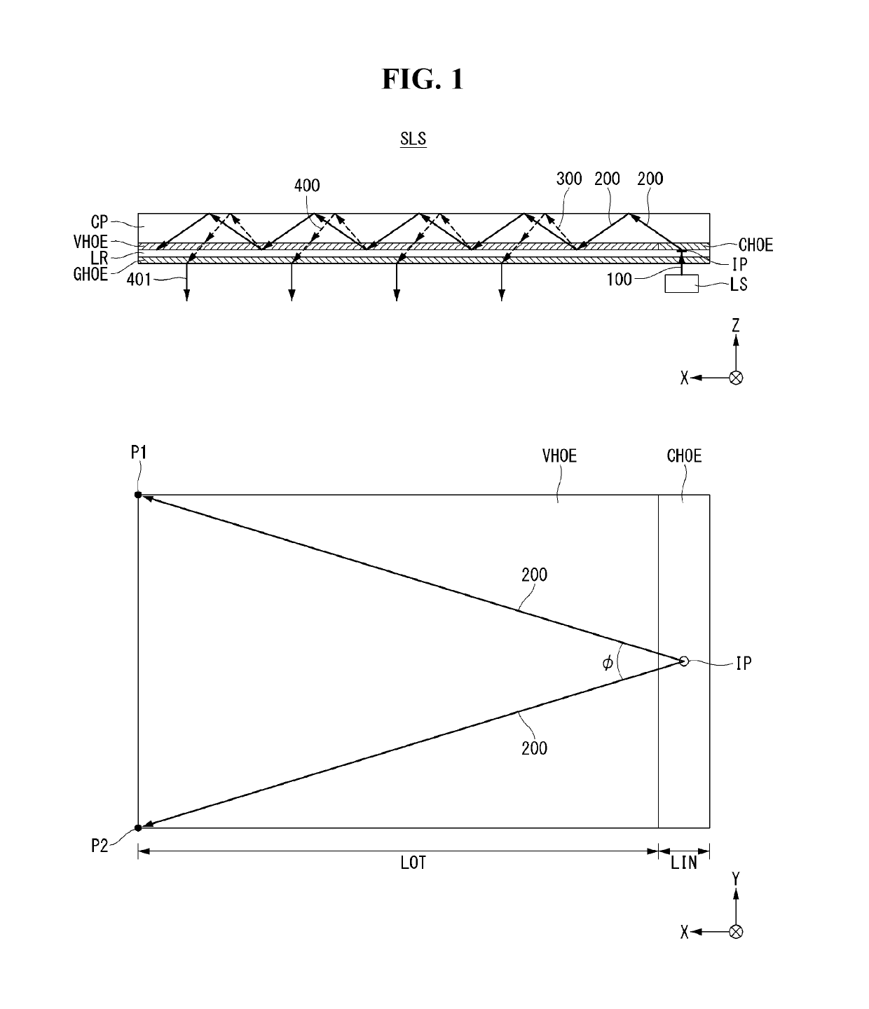
[0036]Referring to FIG. 1, a directional optical unit comprises a directional optical substrate SLS and a light source LS. The directional optical substrate SLS includes a cover plate CP, a light radiating film VHOE, a light incident film CHOE, a low refractive layer LR and a sensing light controlling film GHOE. The cover plate CP may have a rectangular plate shape of which a length, a width and a thickness. In FIG. 1, the length is along to X-axis, the width is along to Y-axis and the thickness is along to Z-axis.

[0037]The directional optical unit is an optical device for providing the collimated light expanded covering a large area corresponding to a surface of the display. Therefore, it is preferable that the light source LS provides a collimated light.

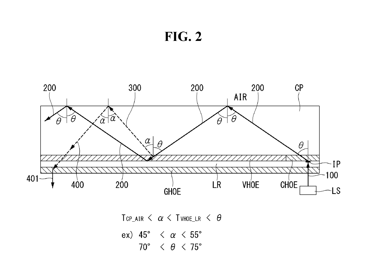
[0038]On the bottom surface of the cover plate CP, the light radiating film VHOE and the light incident film CHOE is attached. The light radiating film VHOE is an optical element for providing the radiating lights 300. It is prefe...

second embodiment

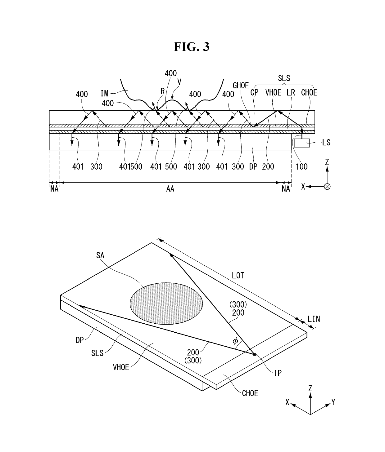
[0079]Further referring to the perspective view shown in the lower portion of FIG. 4, the horizontal collimating film PHOE may be disposed at a light covering part LCO defined at the position being apart with a predetermined distance from the light entering part LIN. In the second embodiment, the image sensing area SA would be substantially same with the light going-out part LOT.

[0080]

[0081]Until now, we explain about the features of the present disclosure based on the directional optical unit for providing the directional lights in the flat panel display embedding an optical image sensor. Hereinafter, we will explain about the application embodiment for the whole structure of the flat panel display embedding an optical image sensor formed by joining the flat display panel with a directional optical unit according to the present disclosure.

[0082]Referring to FIG. 5, we will explain about a flat panel display embedding an optical image sensor according to the first application exampl...


PUM


Abstract

The present disclosure relates to a flat panel display embedding an optical imaging sensor such as a fingerprint image sensor. The present disclosure suggests a flat panel display embedding an image sensor comprising: a display panel including a display area and a non-display area; and a directional optical unit having a length and a width corresponding to the display panel and a thickness, and attached on a top surface of the display panel, wherein the directional optical unit provides a sensing light to the display area, and wherein the sensing light is collimated and directionized to a predetermined direction.

Description

[0001]This application claims the benefit of Korea Patent Application No. 10-2016-0160263 filed on Nov. 29, 2016, which is incorporated herein by reference for all purposes as if fully set forth herein.BACKGROUND[0002]Technical Field[0003]The present disclosure relates to a flat panel display embedding an optical imaging sensor such as a fingerprint image sensor. Especially, the present disclosure relates to a flat panel display embedding an optical imaging sensor including an ultra thin substrate providing the directional lights and an optical imaging sensor.[0004]Description of the Related Art[0005]Various computer based systems including the notebook computer, the tablet personal computer (or, PC), the smart phone, the personal digital assistants, the automated teller machines and / or the search information system have been developed. As these devices use and store the various personal information as well as the business information and the trade secrets, it is required to strengt...

Claims


Application Information

Patent Timeline
Patent Type & Authority Patents(United States)
IPC IPC(8): G02B5/32F21V8/00G06K9/00G06V40/13
CPCG02B6/0035G02B5/32G06K9/00013G02B6/003G02B6/0051G02B6/0018G02B6/0053G02F1/13338G02F1/1335G06F3/0421G06V40/1324G06V40/13G02B6/0011G06F3/0412G06F3/042G06F2203/04109G06V40/12H10K59/65G02B5/0252G02B27/30G02B6/0055G06K2207/1015G06V40/1318
Inventor LEE, GUENSIKCHOO, KYOSEOP
Owner LG DISPLAY CO LTD
Why Eureka
Try Eureka