Flat panel display embedding optical imaging sensor

a technology of optical imaging and flat panel display, which is applied in the direction of planar/plate-like light guides, instruments, mechanical instruments, etc., can solve the problems of limited application of optical fingerprint sensors to various applications such as combining with display devices, and the use of diffused (or diverged) lights having very low directivity, so as to achieve high resolution and sensitivity. , the effect of superiority

Active Publication Date: 2020-02-18
LG DISPLAY CO LTD
View PDF33 Cites 0 Cited by
  • Summary
  • Abstract
  • Description
  • Claims
  • Application Information

AI Technical Summary

Benefits of technology

[0014]In order to overcome the above mentioned drawbacks, a purpose of the present disclosure is to provide a flat panel display embedding an ultra thin optical image sensor (or an optical image recognition apparatus). Another purpose of the present disclosure is to provide a flat panel display having an optical image sensor in which most or all of a surface of the display panel may be used for the sensing area. Still another purpose of the present disclosure is to provide a flat panel display embedding an optical image sensor in which a directional light is used as a sensing light covering a large surface area. Yet another purpose of the present disclosure is to provide a flat panel display embedding an ultra thin and large area optical image sensor of which resolution and sensitivity are very high and / or superior.
[0022]The present disclosure provides a flat panel display embedding an optical image sensor that has a high resolution recognizing ability or sensitivity by providing the directionized lights (or ‘oriented’) as the sensing lights. Comparing with the diffused lights used in the conventional art for the fingerprint sensor, because that the directionized lights according to the present disclosure are used for sensing the image without any loss of lights, the present disclosure has the merits of the higher resolution and the superior sensitivity. The present disclosure provides a flat panel display embedding a large area optical image sensor in which a collimated infrared laser beam is expanded over a large area corresponding to the display panel for the sensing lights using a holography technology. The present disclosure provides a flat panel display having an ultra thin optical image sensor in which a direction light is provided on the display surface within a thin thickness. Further, according to the present disclosure, the protective substrate disposed on the topmost surface is used as the cover substrate of the direction optical substrate. Using a holographic film, the collimated light is provided as covering the large area corresponding to the display surface so that the present disclosure provides an ultra thin direction optical substrate. When joining the optical image sensor to the display device, the whole thickness of the display device is not thicker. As the image sensing area may be set freely within the display area of the display device, the flat panel display embedding an optical image sensor according to the present disclosure may be applied to various applications.

Problems solved by technology

There is a limitation to increasing the size of the object for scanning the image.
Therefore, there are limitations for applying the optical fingerprint sensor to various applications such as combining with the display devices.
However, this optical fingerprint sensor uses the diffused (or diverged) lights having very low directivity.
Therefore, there is a limitation to recognize the exact fingerprint pattern.
When using the collimated lights such as the infrared laser having high directivity, it is very hard to generate the sensing lights to cover the wider area.
Therefore, the fingerprint sensing area is restricted in a small area.
In order to radiate the collimated lights over the wider scan area, specific scanning structure is required, so that this system is not suitable for portable or personal display apparatus.
However, the capacitive fingerprint sensor also has many problems.
Therefore, the structure would be very complex and further the non-display area (or bezel area) may be increased.
However, the detection ability for the difference of the capacitive storage amount for sensing the fingerprint may be deteriorated by the protective film even though its thickness is very thin.
In that case, the recognition ability may be deteriorated.
That is, the total thickness of the cover glass may affect the sensitivity of the capacitive fingerprint sensor.
In the interim, the diffused lights used in the sensing light source may affect the sensitivity of the optical fingerprint sensor.
When using the collimated lights for enhancing the sensitivity of the optical fingerprint sensor, the bulky and / or complex optical devices are required so that it is very hard to apply to a display for personal mobile device.

Method used


Image

  • Flat panel display embedding optical imaging sensor
  • Flat panel display embedding optical imaging sensor
  • Flat panel display embedding optical imaging sensor

Examples


first embodiment

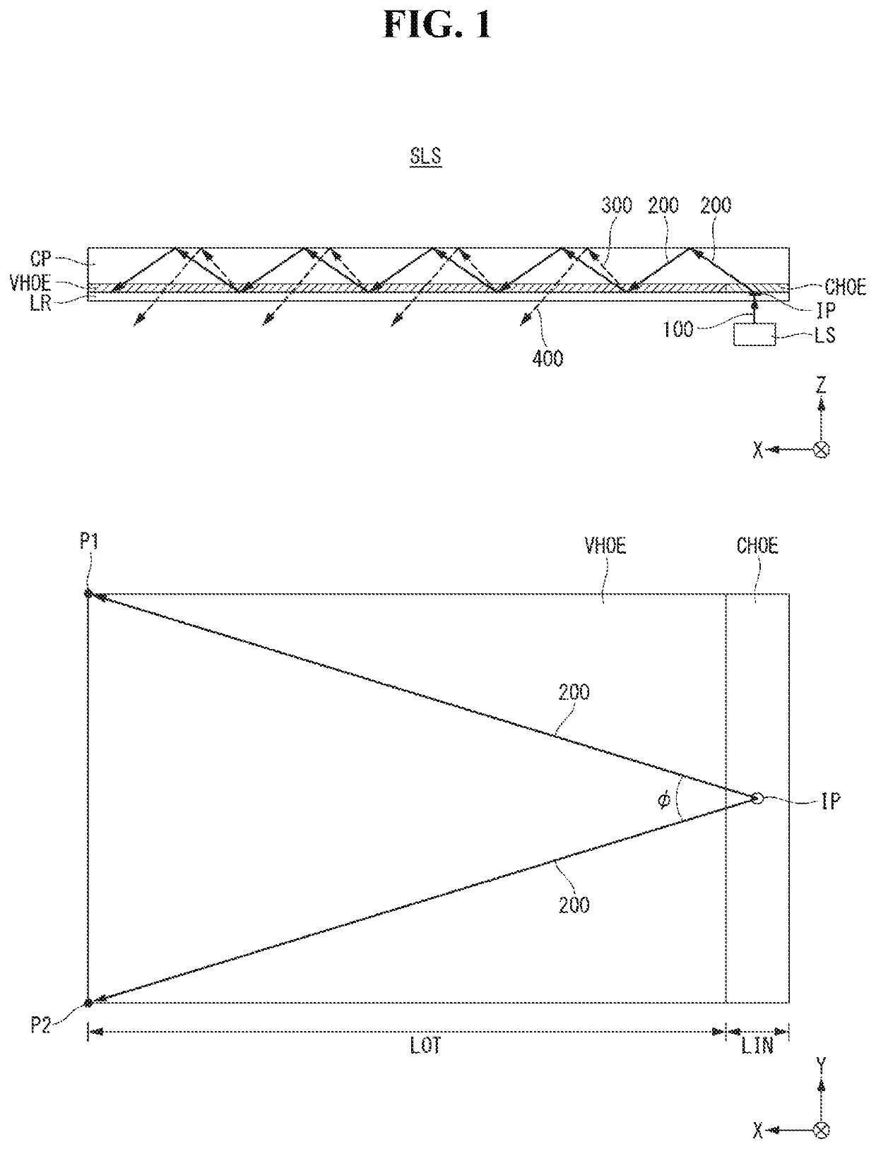
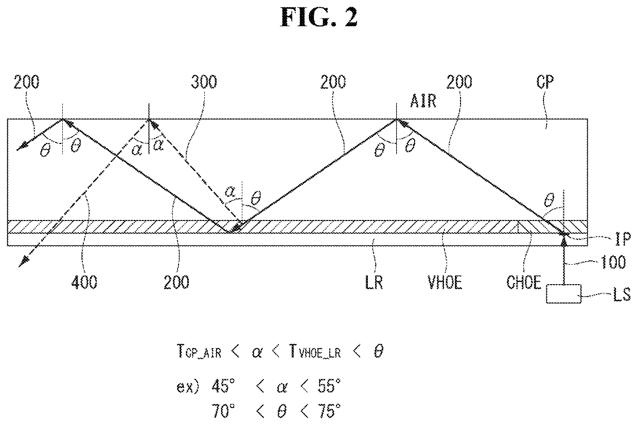
[0037]Hereinafter, referring to FIGS. 1 and 2, a first embodiment of the present disclosure will be described. FIG. 1 is a drawing illustrating a structure of a directional optical substrate applied for a flat panel display embedding an optical image sensor according to the first embodiment of the present disclosure. In FIG. 1, the upper drawing is a side view on the XZ plane and the lower drawing is a plane view on the XY plane.

[0038]Referring to FIG. 1, a directional optical unit according to the first embodiment comprises a directional optical substrate SLS and a light source LS. The directional optical substrate SLS includes a cover plate CP, a light radiating film VHOE, a light incident film CHOE and a low refractive layer LR. The cover plate CP may have a rectangular plate shape of a length, a width and a thickness. In FIG. 1, the length is along X-axis, the width is along Y-axis and the thickness is along Z-axis.

[0039]The directional optical unit is an optical device for prov...

second embodiment

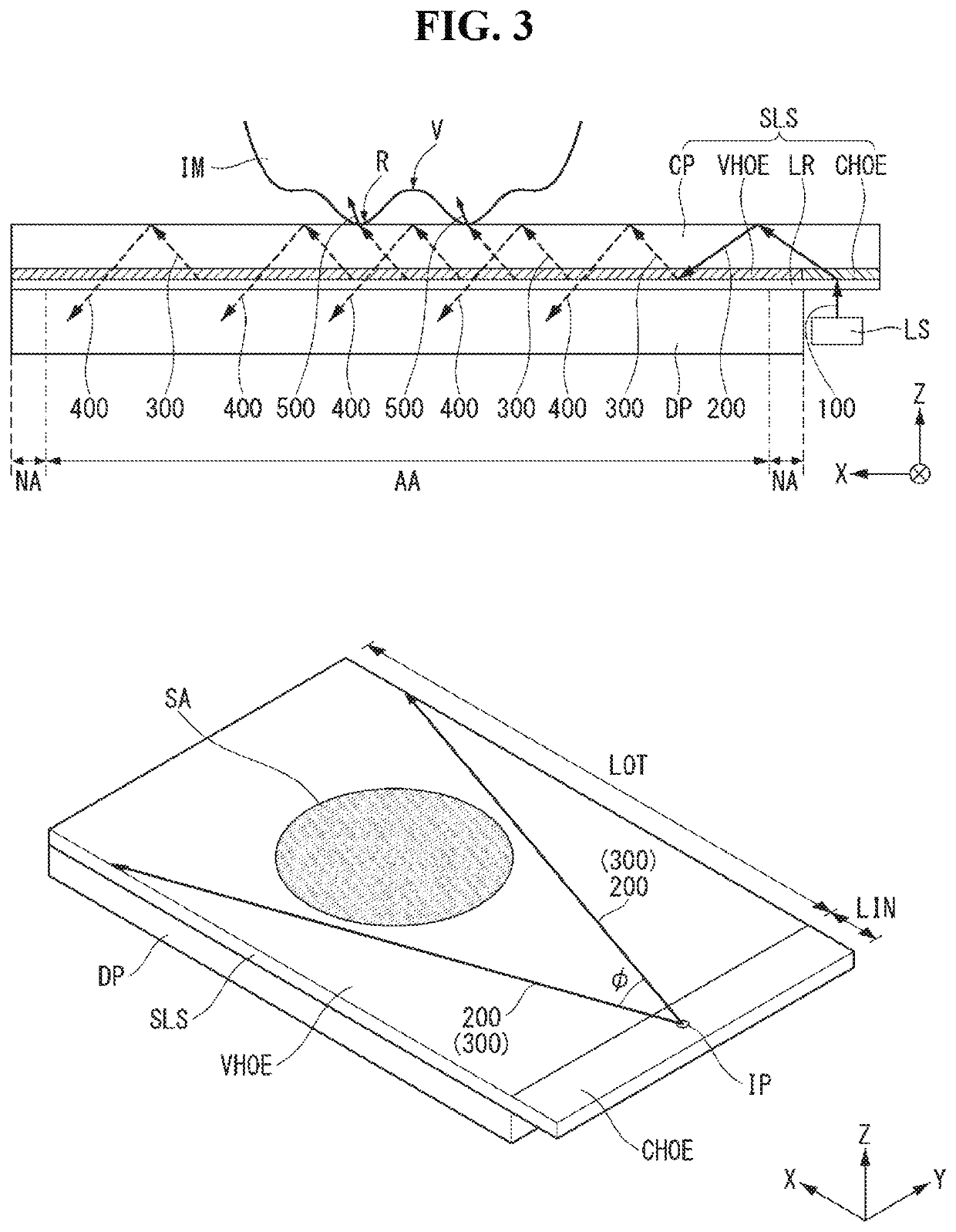
[0071]Hereinafter, referring to FIG. 4, we will explain about the second embodiment of the present disclosure. FIG. 4 is a drawing illustrating a structure of a flat panel display embedding an optical image sensor including a directional optical unit and an optical sensor, according to the second embodiment of the present disclosure.

[0072]In the second embodiment of the present disclosure, we will explain about the case in which the image sensing area SA is much wider than the first embodiment. Specifically, most of the display area AA may be defined as the image sensing area SA.

[0073]The flat panel display embedding the optical image sensor is basically similar with the first embodiment. The different point is that the flat panel display embedding the optical image sensor according to the second embodiment further comprises a horizontal collimating film PHOE for collimating the expanded propagating light 200 on the XY plane as having the collimated width corresponding to the width ...

third embodiment

[0077]Hereinafter, referring to FIG. 5, we will explain about the third embodiment of the present disclosure. FIG. 5 is a drawing illustrating a structure of a flat panel display embedding an optical image sensor including a directional optical unit and an optical sensor, according to the third embodiment of the present disclosure.

[0078]In the third embodiment, the whole of the display area AA of the display panel DP would be used for the image sensing area SA. The flat panel display embedding an optical image sensor is very similar with the second embodiment. The difference is that the horizontal collimating film PHOE is disposed at the opposite end non-display area NA of the cover plate CP facing with the light incident film CHOE. Further, the radiating lights 300 are provided as the propagating light 200 goes back to the light incident film CHOE from the horizontal collimated film PHOE.

[0079]The flat panel display embedding an optical image sensor according to the third embodimen...


PUM

PropertyMeasurementUnit
incident angleaaaaaaaaaa
refractive indexaaaaaaaaaa

Abstract

The present disclosure relates to a flat panel display embedding an optical imaging sensor such as a fingerprint image sensor. The present disclosure suggests a flat panel display embedding an image sensor comprising: a display panel including a display area and a non-display area; and a directional optical unit having a length and a width corresponding to the display panel and a thickness, and attached on a top surface of the display panel, wherein the directional optical unit provides a sensing light to the display area, and wherein the sensing light is collimated and directionized to a predetermined direction.

Description

BACKGROUNDTechnical Field[0001]The present disclosure relates to a flat panel display embedding an optical imaging sensor such as a fingerprint image sensor. In particular, the present disclosure relates to a flat panel display embedding an optical imaging sensor including an ultra thin substrate providing the directional lights and an optical imaging sensor.Description of the Related Art[0002]Various computer based systems including the notebook computer, the tablet personal computer (or, PC), the smart phone, the personal digital assistants, the automated teller machines and / or the search information system have been developed. As these devices use and store the various personal information as well as the business information and the trade secrets, it is desirable to strengthen the securities for preventing these important data being leaked.[0003]To do so, one method has been suggested for strengthening the security using an image sensor recognizing the authorized user's biologica...

Claims


Application Information

Patent Timeline
Patent Type & Authority Patents(United States)
IPC IPC(8): G06F3/042H01L27/32G02B6/10G02B5/32G06K9/00F21V8/00G02B6/12G02F1/1333G06F3/041
CPCG02B6/12004G06K9/00013G06K9/00046G02B5/32G02B6/0035H01L27/3234G02B6/102G06F3/042G02F1/13338G06F3/0412G02B6/002G02B6/0016G06F2203/04109G06K9/0008G06F1/1626G06F1/1684G06F2200/1612G06V40/1306G06V40/1324G06V40/1359G02F1/1335G06V40/1318H10K59/00H10K59/65
Inventor BANG, HYUNGSEOKKIM, CHEOLSELEE, BUYEOL
Owner LG DISPLAY CO LTD
Why Eureka
Try Eureka