Thin flat type optical imaging sensor and flat panel display embedding the same

a flat panel display and optical imaging technology, applied in the field of display devices, can solve the problems of limited application of optical fingerprint sensors to various applications such as combining with display devices, using diffused (or diverged) light having very low directivity, and achieves high resolution, superior sensitivity, and recognition ability or sensitivity. high

Active Publication Date: 2020-02-18
LG DISPLAY CO LTD
View PDF10 Cites 1 Cited by
  • Summary
  • Abstract
  • Description
  • Claims
  • Application Information

AI Technical Summary

Benefits of technology

[0015]In order to overcome the above mentioned drawbacks, the purpose of the present disclosure is to suggest a flat panel display embedding an ultra-thin optical image sensor (or an optical image recognition apparatus). Another purpose of the present disclosure is to suggest a flat panel display having an optical image sensor in which most of all or whole surface of the display panel would be used for the sensing area. Still another purpose of the present disclosure is to suggest a flat panel display embedding an optical image sensor in which a directional light is used as a sensing light covering large surface. Yet another purpose of the present disclosure is to suggest a flat panel display embedding an ultra-thin and large area optical image sensor of which resolution and sensitivity are very high and / or superior.
[0017]In another aspect of the present disclosure, a portable electronic device including a display panel with an embedded image sensor comprises a display area displaying an image on the display panel; a low refractive layer on the display panel and refracting incident light; a cover plate having a sensing area and receiving the incident light; a light source providing the cover plate with the incident light through the low refractive layer; a light incident film receiving the incident light and expanding the received incident light corresponding to an area for the cover plate; a light radiating film directing the expanded incident light to an object to detect an image of the object and corresponding to the sensing area of the cover plate; and a light sensor receiving the image detected light traveling through the cover plate and the low refractive layer, wherein the expanded incident light propagates with repeating an internal total reflection in the cover plate without substantially losing an amount of the incident light.
[0024]The present disclosure suggests a flat panel display embedding an optical image sensor that has a high resolution recognizing ability or sensitivity by providing the directionized light (or ‘oriented’) as the sensing light. Comparing with the diffused light used in the conventional art for the fingerprint sensor, because that the directionized light according to the present disclosure are used for sensing the image without any loss of light so that the present disclosure has the merits of the higher resolution and the superior sensitivity. The present disclosure suggests a flat panel display embedding a large area optical image sensor in which a collimated infrared laser beam is expanded over a large area corresponding to the display panel for the sensing light using a holography technology. The present disclosure suggests a flat panel display having an ultra-thin optical image sensor in which a directional light is provided on the display surface within a thin thickness. Further, according to the present disclosure, the protective substrate disposed on the topmost surface is used as the cover substrate of the direction optical substrate. Using a holographic film, the collimated light is provided as covering the large area corresponding to the display surface so that the present disclosure suggests an ultra-thin direction optical substrate. When joining the optical image sensor to the display device, the whole thickness of the display device is not thicker. As the image sensing area may be set freely within the display area of the display device, the flat panel display embedding an optical image sensor according to the present disclosure may be applied various applications.

Problems solved by technology

There is a limitation to increasing the size of the object for scanning the image.
Therefore, there are limitations to applying the optical fingerprint sensor to various applications such as combining with the display devices.
However, this optical fingerprint sensor uses the diffused (or diverged) light having very low directivity.
Therefore, there is a limitation to recognizing the exact fingerprint pattern.
When using the collimated light such as the infrared laser having high directivity, it is difficult to generating the sensing light as covering the wider area.
In order to radiate the collimated light over the wider scan area, specific scanning structure is required, so that this system is not suitable for portable or personal display apparatus.
However, the capacitive fingerprint sensor also has many problems.
Therefore, the structure becomes very complex and further the non-display area (or bezel area) is increased.
In some cases, the push button (i.e., the home key of the smart phone) overlaps the fingerprint sensor, so that the thickness of the whole device becomes too thick.
However, the detection capability for the difference of the capacitive storage amount for sensing the fingerprint can be deteriorated by the protective film even though its thickness is very thin.
In that case, the recognition capability can be deteriorated.
That is, the total thickness of the cover glass may affect the sensitivity of the capacitive fingerprint sensor.
In the interim, the diffused light used in the sensing light source may affect the sensitivity of the optical fingerprint sensor.
When using the collimated light for enhancing the sensitivity of the optical fingerprint sensor, the bulky and / or complex optical devices are required so that it is difficult to apply to a display for personal mobile device.

Method used


Image

  • Thin flat type optical imaging sensor and flat panel display embedding the same
  • Thin flat type optical imaging sensor and flat panel display embedding the same
  • Thin flat type optical imaging sensor and flat panel display embedding the same

Examples


Embodiment Construction

[0032]Referring to attached figures, we will explain various aspects of the present disclosure. Like reference numerals designate like elements throughout the detailed description. However, the present disclosure is not restricted by these aspects but can be applied to various changes or modifications without changing the technical spirit. In the following aspects, the names of the elements are selected by considering the easiness for explanation so that they may be different from actual names.

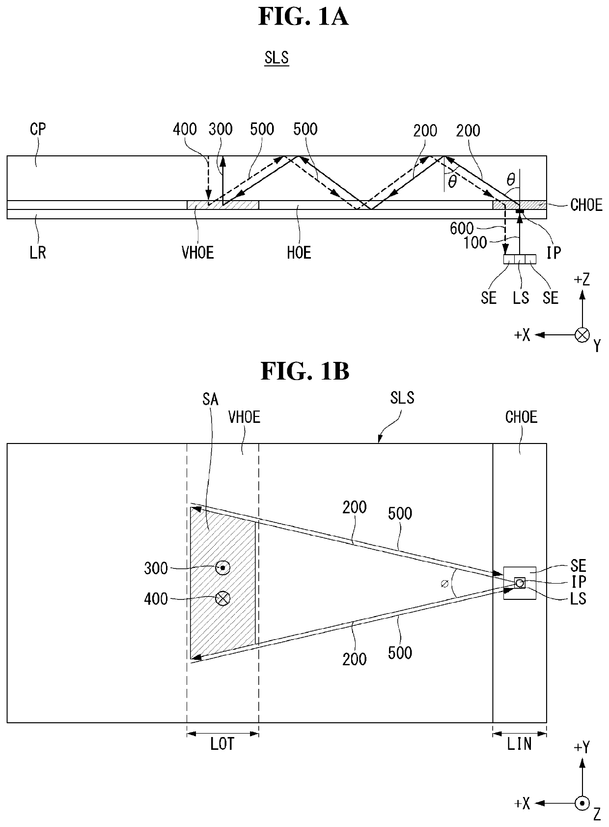
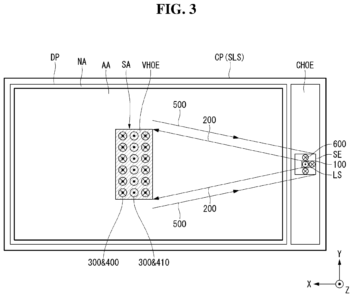
[0033]Hereinafter, with reference to FIGS. 1A and 1B, an aspect of the present disclosure will be described. FIGS. 1A and 1B are drawings illustrating a structure of a directional optical unit applied for a flat panel display embedding an optical image sensor according to an aspect of the present disclosure. More specifically, FIG. 1A is a side view on the XZ plane and FIG. 1B is a plan view on the XY plane.

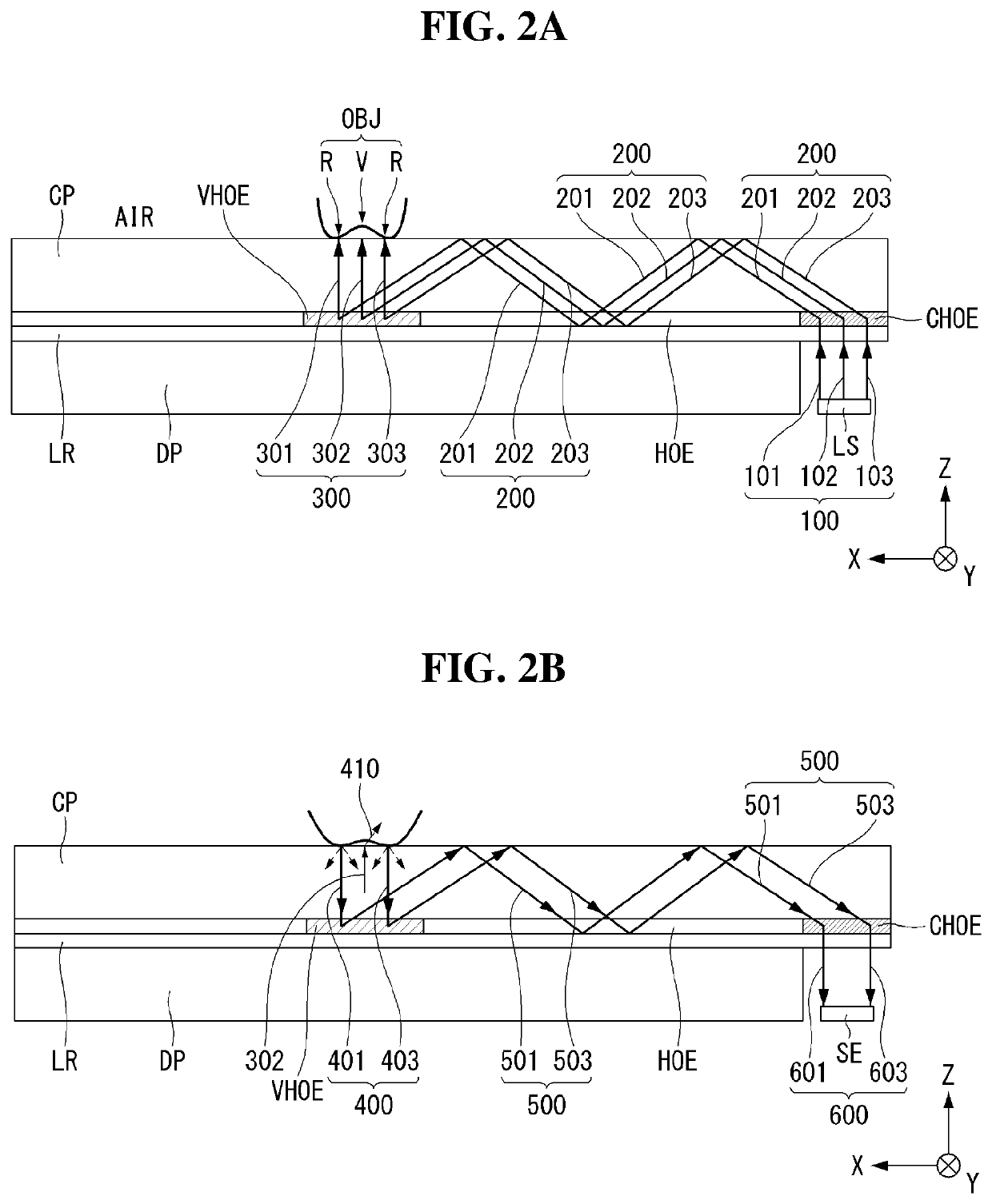
[0034]Referring to FIGS. 1A and 1B, a directional optical unit according to an aspect c...


PUM

PropertyMeasurementUnit
refractive indexaaaaaaaaaa
radiusaaaaaaaaaa

Abstract

The present disclosure relates to a flat panel display embedding an optical imaging sensor such as a fingerprint image sensor. The present disclosure suggests a flat panel type optical image sensor comprising: a cover plate having a sensing area; a light incident film disposed at a side under the cover plate; a light radiating film disposed under the cover plate corresponding to the sensing area; a low refractive layer under the light incident film and the light radiating film; a light source disposed under the light incident film; and a light sensor disposed under the light incident film.

Description

CROSS-REFERENCE TO RELATED APPLICATION[0001]This application claims the benefit of Korea Patent Application No. 10-2016-0162214 filed on Nov. 30, 2016, which is incorporated herein by reference in its entirety for all purposes as if fully set forth herein.BACKGROUNDField of the Disclosure[0002]The present disclosure relates to a display device, and more particularly, to a flat panel display embedding an optical imaging sensor such as a fingerprint image sensor. Especially, the present disclosure relates to a thin flat type optical image sensor and a flat panel display embedding the same optical imaging sensor.Description of the Background[0003]Various computer based systems including a notebook computer, a tablet personal computer (or, PC), the smart phone, personal digital assistants, automated teller machines (ATM) and / or search information system have been developed. As these devices use and store the various personal information as well as the business information and the confid...

Claims


Application Information

Patent Timeline
Patent Type & Authority Patents(United States)
IPC IPC(8): G06K9/00G01J1/42H01L27/146F21V8/00
CPCG02B6/0091H01L27/14678G02B6/0035G06K9/00013G02B6/0015G01J1/42G09F9/00G06V40/1318G02B6/0018G02B6/0055G02B6/0063G02B6/0073
Inventor RYU, SEUNGMANYOON, ARA
Owner LG DISPLAY CO LTD
Why Eureka
Try Eureka