Flat Panel Display Having Optical Imaging Sensor

a flat panel display and optical imaging technology, applied in the field of flat panel display having optical imaging sensors, can solve the problems of limited application of optical fingerprint sensors to various applications such as combining with display devices, using diffused (or diverged) lights having very low directivity, and limiting the size of objects, etc., to achieve superior sensitivity, high resolution, and high resolution. the effect of ability or sensitivity

Active Publication Date: 2018-11-08
LG DISPLAY CO LTD
View PDF0 Cites 1 Cited by
  • Summary
  • Abstract
  • Description
  • Claims
  • Application Information

AI Technical Summary

Benefits of technology

[0016]In order to overcome the above mentioned drawbacks, a purpose of the present disclosure is to provide a flat panel display having an ultra thin optical image sensor (or an optical image recognition apparatus). Another purpose of the present disclosure is to provide a flat panel display having an optical image sensor in which most or all of a surface of the display panel may be used for the sensing area. Still another purpose of the present disclosure is to provide a flat panel display having an optical image sensor in which a directional light is used as a sensing light covering a large surface area. Yet another purpose of the present disclosure is to provide a flat panel display having an ultra thin and large area optical image sensor of which resolution and sensitivity are very high and / or superior, by using a directional light and by maximizing the light efficiency. Still yet another purpose of the present disclosure is to provide a flat panel display having an optical image sensor in which the sensing accuracy is enhanced by eliminating the light noise caused by the scattering of the sensing light inside of the display panel.
[0024]The present disclosure provides a flat panel display having an optical image sensor that has a high resolution recognizing ability or sensitivity by providing the directionized lights (or ‘oriented’) as the sensing lights. Comparing with the diffused lights used in the conventional art for the fingerprint sensor, because that the directionized lights according to the present disclosure are used for sensing the image without any loss of lights, the present disclosure has the merits of the higher resolution and the superior sensitivity. The present disclosure provides a flat panel display having a large area optical image sensor in which a collimated infrared laser beam is expanded over a large area corresponding to the display panel for the sensing lights using a holography technology. The present disclosure provides a flat panel display having an ultra thin optical image sensor in which a direction light is provided on the display surface within a thin thickness. Specifically, by making the sensing light to enter into the surface of the image sensor vertically, the light amount or intensity of the sensing light is not reduced so that more accurate recognition result can be acquired. Further, it is possible to maximize the accuracy of the image sensing results by eliminating the noise lights caused by scattering as the light is passing through the display panel, and by selectively inputting only the sensing lights satisfying a predetermined incident angle condition vertically to the image sensor.

Problems solved by technology

There is a limitation to increasing the size of the object for scanning the image.
Therefore, there are limitations for applying the optical fingerprint sensor to various applications such as combining with the display devices.
However, this optical fingerprint sensor uses the diffused (or diverged) lights having very low directivity.
Therefore, there is a limitation to recognize the exact fingerprint pattern.
When using the collimated lights such as the infrared laser having high directivity, it is very hard to generate the sensing lights to cover the wider area.
Therefore, the fingerprint sensing area is restricted in a small area.
In order to radiate the collimated lights over the wider scan area, specific scanning structure is required, so that this system is not suitable for portable or personal display apparatus.
However, the capacitive fingerprint sensor also has many problems.
Therefore, the structure would be very complex and further the non-display area (or bezel area) may be increased.
However, the detection ability for the difference of the capacitive storage amount for sensing the fingerprint may be deteriorated by the protective film even though its thickness is very thin.
In that case, the recognition ability may be deteriorated.
When using the collimated lights for enhancing the sensitivity of the optical fingerprint sensor, the bulky and / or complex optical devices are required so that it is very hard to apply to a display for personal mobile device.

Method used


Image

  • Flat Panel Display Having Optical Imaging Sensor
  • Flat Panel Display Having Optical Imaging Sensor
  • Flat Panel Display Having Optical Imaging Sensor

Examples


first embodiment

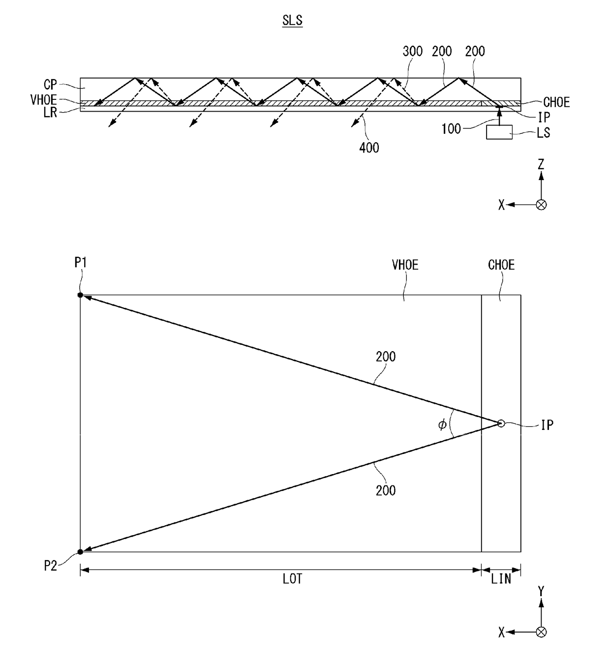
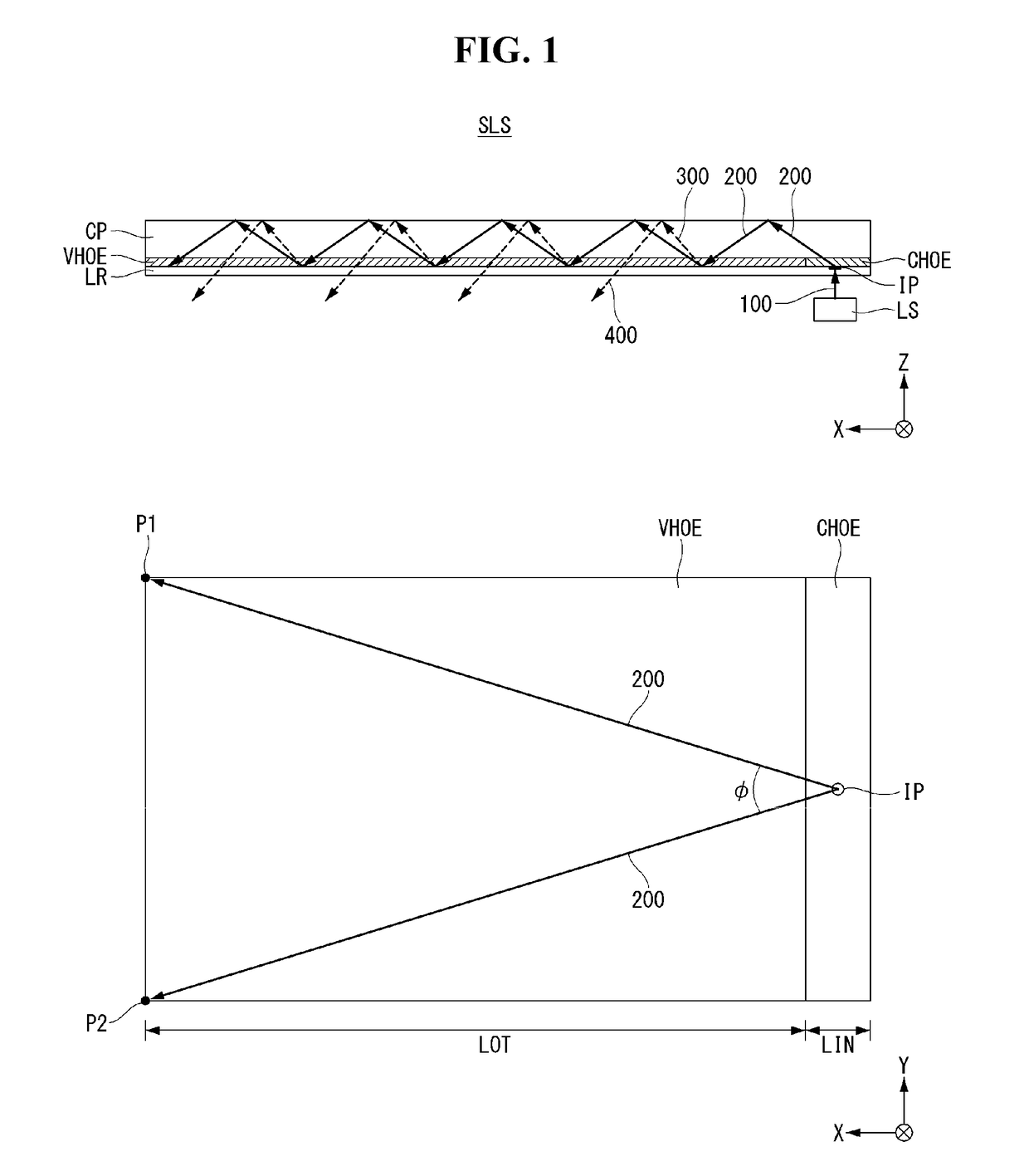
[0033]Hereinafter, referring to FIGS. 1 and 2, a first embodiment of the present disclosure will be described. FIG. 1 is a drawing illustrating a structure of a directional optical substrate applied for a flat panel display having an optical image sensor according to the first embodiment of the present disclosure. In FIG. 1, the upper drawing is a side view on the XZ plane and the lower drawing is a plane view on the XY plane.

[0034]Referring to FIG. 1, a directional optical unit according to the first embodiment comprises a directional optical substrate SLS and a light source LS. The directional optical substrate SLS includes a cover plate CP, a light radiating film VHOE, a light incident film CHOE and a low refractive layer LR. The cover plate CP may have a rectangular plate shape of which a length, a width and a thickness. In FIG. 1, the length is along to X-axis, the width is along to Y-axis and the thickness is along to Z-axis.

[0035]The directional optical substrate SLS is an op...

second embodiment

[0071]Referring to FIG. 4, we will explain about a structure for maximizing the light efficiency in the flat panel display having an optical image sensor according to the second embodiment of the present disclosure. FIG. 4 is a cross-sectional view illustrating a structure of a flat panel display having an optical image sensor in which the light accuracy is maximized, according to the second embodiment of the present disclosure.

[0072]Referring to FIG. 4, a flat panel display having an optical image sensor according to the second embodiment of the present disclosure comprises a display panel DP, a directional optical substrate SLS, a light source LS and an image photo sensor (or ‘image sensor’) SE. Especially, a sensing light control film GHOE and an ultra low refractive layer LRA are disposed between the display panel DP and the image sensor SE.

[0073]The display panel DP includes a display area AA and a non-display area NA. The display area AA may be disposed at the middle portions ...

third embodiment

[0090]Referring to FIG. 6, we will explain about the third embodiment of the present disclosure. In the third embodiment, the flat panel display may have an image sensor SE having the different structure from the second embodiment. In the third embodiment, a volumetric photo image sensor SE not the thin film type is equipped with the flat panel display. For the flat panel display having the photo image sensor according to the third embodiment of the present disclosure may have a directional optical unit same as the first and second embodiments, so that the structure for the directional optical unit may not be duplicated in convenience. FIG. 6 is an enlarged cross-sectional view illustrating a structure of a flat panel display having an optical image sensor in which the light accuracy is maximized, according to the third embodiment of the present disclosure.

[0091]Referring to FIG. 6, the sensing light control film GHOE is attached under the bottom surface of the display panel DP. The...


PUM


Abstract

The present disclosure relates to a flat panel display having an optical imaging sensor such as a fingerprint image sensor. The present disclosure provides a flat panel display having an image sensor comprising: a display panel including a display area and a non-display area, the display panel having a top surface; a directional optical unit attached to the top surface of the display panel, the directional optical unit having a length along a length axis of the display panel, a width along a width axis of the display panel and a thickness along a thickness axis of the display panel; a sensing light control film disposed under the display panel; and an image sensor disposed under the sensing light control film.

Description

CROSS-REFERENCE TO RELATED APPLICATIONS[0001]This application claims the benefit of Republic of Korea Patent Application No. 10-2017-0056314 filed on May 2, 2017, which is incorporated herein by reference in its entirety.BACKGROUNDTechnical Field[0002]The present disclosure relates to a flat panel display having an optical imaging sensor such as a fingerprint image sensor. In particular, the present disclosure relates to a flat panel display having an optical imaging sensor including an ultra thin substrate providing the directional lights and an optical imaging sensor.Description of the Related Art[0003]Various computer based systems including the notebook computer, the tablet personal computer (or, PC), the smart phone, the personal digital assistants, the automated teller machines and / or the search information system have been developed. As these devices use and store the various personal information as well as the business information and the trade secrets, it is desirable to st...

Claims


Application Information

Patent Timeline
Patent Type & Authority Applications(United States)
IPC IPC(8): G06K9/00G02B5/32
CPCG06K9/0002G02B5/32G06K9/00087G06F1/1643G06V40/1324G06V40/1318G06F1/1684G06F1/1601G06F3/044G06V40/1306G06V40/1365
Inventor RYU, SEUNGMANLEE, GUENSIKHYUN, JOOBONGYOON, ARA
Owner LG DISPLAY CO LTD
Why Eureka
Try Eureka