Flat panel display embedding optical imaging sensor

a technology of optical imaging and display screen, which is applied in the direction of identification means, instruments, polarising elements, etc., can solve the problems of limited application of optical fingerprint sensors to various applications such as combining with display devices, using diffused (or diverged) lights having very low directivity, and achieves resolution and sensitivity very high and/or superior

Active Publication Date: 2019-08-27
LG DISPLAY CO LTD
View PDF31 Cites 1 Cited by
  • Summary
  • Abstract
  • Description
  • Claims
  • Application Information

AI Technical Summary

Benefits of technology

[0018]In order to overcome the above mentioned drawbacks, a purpose of the present disclosure is to provide a flat panel display embedding an ultra thin optical image sensor (or an optical image recognition apparatus). Another purpose of the present disclosure is to provide a flat panel display having an optical image sensor in which most or all of a surface of the display panel may be used for the sensing area. Still another purpose of the present disclosure is to provide a flat panel display embedding an optical image sensor in which a directional light beam is used as a sensing light covering a large surface area. Yet another purpose of the present disclosure is to provide a flat panel display embedding an ultra thin and large area optical image sensor of which resolution and sensitivity are very high and / or superior.
[0026]The present disclosure provides a flat panel display embedding an optical image sensor that has a high resolution recognizing ability or sensitivity by providing the directionized lights (or ‘oriented’) as the sensing lights, which can also be characterized as light beams. Comparing with the diffused lights used in the conventional art for the fingerprint sensor, because that the directionized lights according to the present disclosure are used for sensing the image without any loss of lights, the present disclosure has the merits of the higher resolution and the superior sensitivity. The present disclosure provides a flat panel display embedding a large area optical image sensor in which a collimated infrared laser beam is expanded over a large area corresponding to the display panel for the sensing lights using a holography technology. The present disclosure provides a flat panel display having an ultra thin optical image sensor in which a direction light is provided on the display surface within a thin thickness. Further, the present disclosure provides a flat panel display embedding an optical image recognition sensor that maximizes the light efficiency and has high performance recognition capability by using a light source that provides the polarized light parallel to the polarization axis of the holographic element.

Problems solved by technology

There is a limitation to increasing the size of the object for scanning the image.
Therefore, there are limitations for applying the optical fingerprint sensor to various applications such as combining with the display devices.
However, this optical fingerprint sensor uses the diffused (or diverged) lights having very low directivity.
Therefore, there is a limitation to recognize the exact fingerprint pattern.
When using the collimated lights such as the infrared laser having high directivity, it is very hard to generate the sensing lights to cover the wider area.
Therefore, the fingerprint sensing area is restricted in a small area.
In order to radiate the collimated lights over the wider scan area, specific scanning structure is required, so that this system is not suitable for portable or personal display apparatus.
However, the capacitive fingerprint sensor also has many problems.
Therefore, the structure would be very complex and further the non-display area (or bezel area) may be increased.
However, the detection ability for the difference of the capacitive storage amount for sensing the fingerprint may be deteriorated by the protective film even though its thickness is very thin.
In that case, the recognition ability may be deteriorated.
When using the collimated lights for enhancing the sensitivity of the optical fingerprint sensor, the bulky and / or complex optical devices are required so that it is very hard to apply to a display for personal mobile device.

Method used


Image

  • Flat panel display embedding optical imaging sensor
  • Flat panel display embedding optical imaging sensor
  • Flat panel display embedding optical imaging sensor

Examples


first embodiment

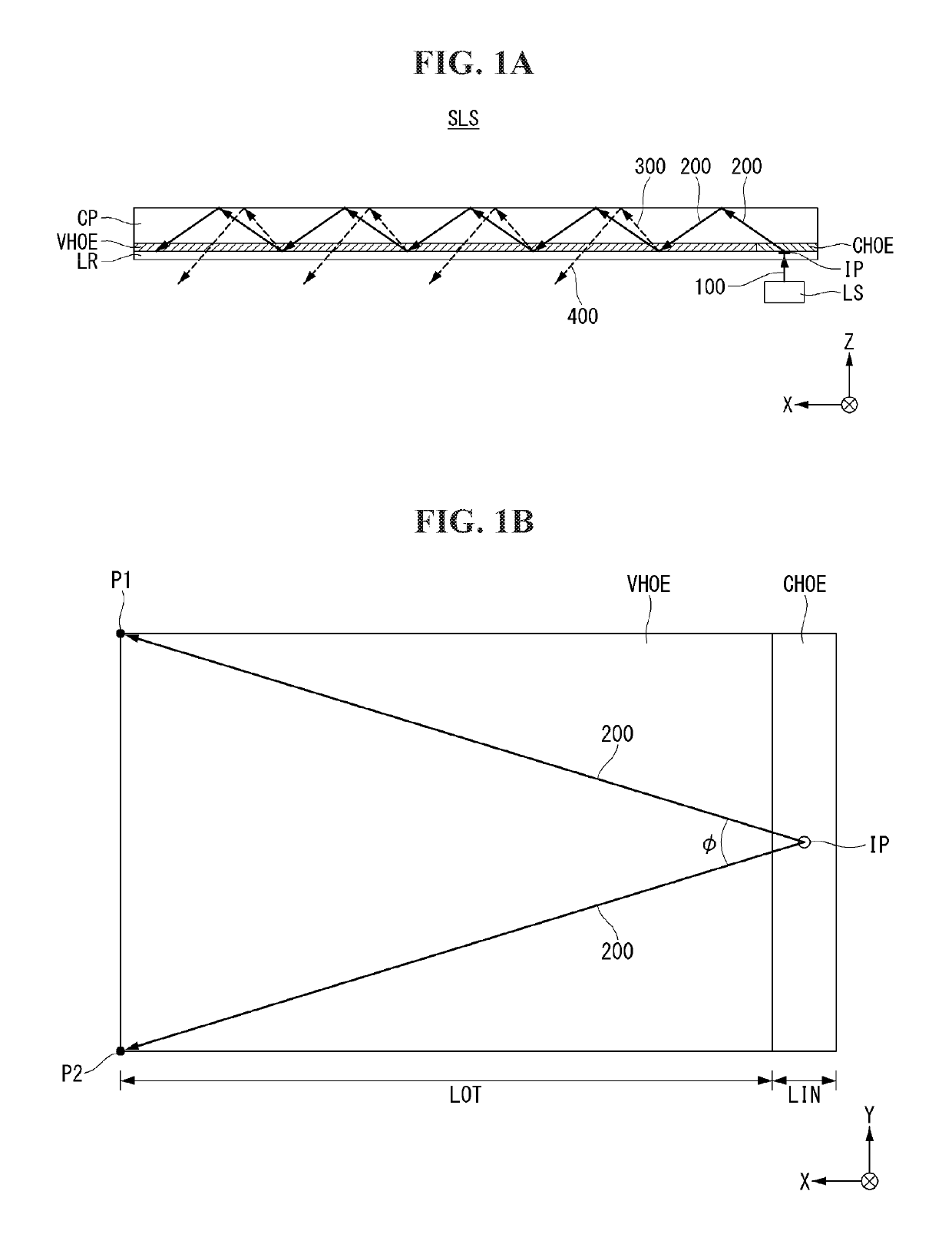
[0038]Referring to FIGS. 1A and 1B, a directional optical unit comprises a directional optical substrate SLS and a light source LS. The directional optical substrate SLS includes a cover plate CP, a light radiating film VHOE, a light incident film CHOE and a low refractive layer LR. The cover plate CP may have a rectangular plate shape of which a length, a width and a thickness. In FIG. 1, the length is along to X-axis, the width is along to Y-axis and the thickness is along to Z-axis.

[0039]The directional optical substrate SLS is an optical device for providing the collimated light expanded covering a large area corresponding to a surface of the display. Therefore, it is preferable that the light source LS provides a collimated light. For example, the light source LS may be a laser diode providing the infra red laser beam. Since the infra red laser beam is very highly collimated, it is very suitable as the light source LS for the directional light unit according to the present dis...

second embodiment

[0085]Referring to FIG. 5A, a directional optical unit comprises a directional optical substrate SLS and a light source LS. The directional optical substrate SLS includes a cover plate CP, a light radiating film VHOE and a light incident film CHOE. The cover plate CP may have a rectangular plate shape of which a length, a width and a thickness. In FIG. 5A, the length is along to X-axis, the width is along to Y-axis and the thickness is along to Z-axis.

[0086]The directional optical substrate SLS is an optical device to provide the sensing light for detecting the image by expanding restrict within a sensing area (or ‘detecting area’) and to provide the sensed light for reproducing the image. The light source LS may be same as the first embodiment.

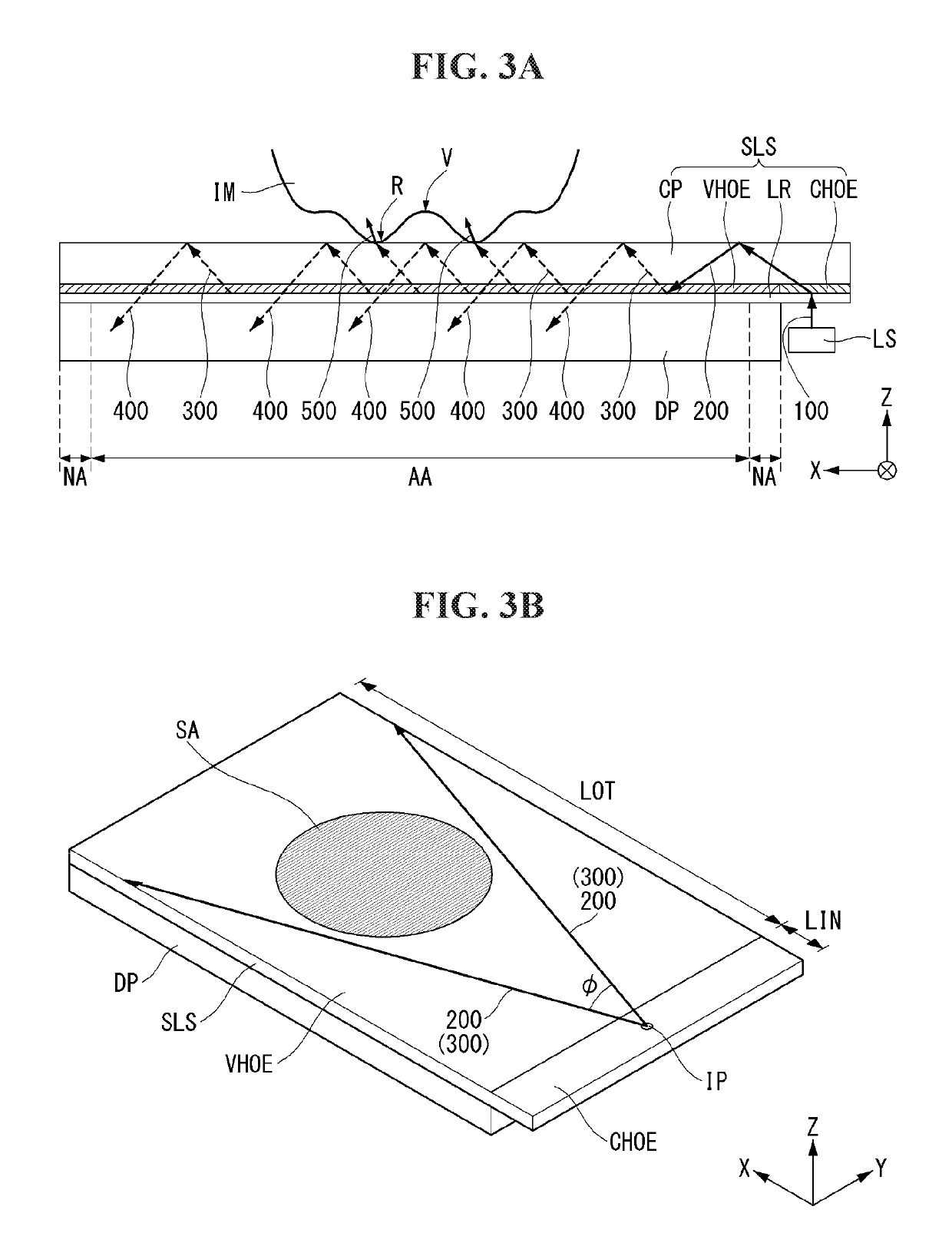
[0087]On the upper surface of the cover plate CP, a sensing area SA (or ‘detecting area’) is defined. When applying with the fingerprint sensor, it is preferable that the sensing area SA is set a position suitable for the user to place user'...


PUM

PropertyMeasurementUnit
sizesaaaaaaaaaa
expanding angleaaaaaaaaaa
refractive indexaaaaaaaaaa

Abstract

The present disclosure relates to a flat panel display embedding an optical imaging sensor such as a fingerprint image sensor. The present disclosure suggests a flat panel display embedding an image sensor comprising: a display panel including a display area and a non-display area; and a directional optical unit having a length and a width corresponding to the display panel and a thickness, and attached on a top surface of the display panel, wherein the directional optical unit provides a sensing light beam to the display area, and wherein the sensing light is collimated and directionized to a predetermined direction.

Description

CROSS REFERENCE TO RELATED APPLICATION(S)[0001]This application claims the benefit of Korea Patent Application No. 10-2017-0056309, filed May 2, 2017, which is incorporated herein by reference for all purposes as if fully set forth herein.BACKGROUND[0002]Technical Field[0003]The present disclosure relates to a flat panel display embedding an optical imaging sensor such as a fingerprint image sensor. In particular, the present disclosure relates to a flat panel display embedding an optical imaging sensor including an ultra thin substrate providing the directional lights and an optical imaging sensor.[0004]Description of the Related Art[0005]Various computer based systems including the notebook computer, the tablet personal computer (or, PC), the smart phone, the personal digital assistants, the automated teller machines and / or the search information system have been developed. As these devices use and store the various personal information as well as the business information and the ...

Claims


Application Information

Patent Timeline
Patent Type & Authority Patents(United States)
IPC IPC(8): G06K9/00G02F1/1333H01L27/00H01L27/30G06F21/32H01L27/32F21V8/00G02B5/32G02F1/1335
CPCG09F9/00G06V40/1306G02B6/005G06F21/32G02B5/3083G02F1/13338G02B5/32G06V40/1318H10K39/32H10K59/65G06F1/1684G06F1/1601G02B5/30G06V40/12G02F1/133528G02B6/0055
Inventor LEE, GUENSIKCHOO, KYOSEOPRYU, SEUNGMAN
Owner LG DISPLAY CO LTD
Why Eureka
Try Eureka