
Accessory for conducting patella surgery

a technology for patella surgery and accessory, which is applied in the field of accessory for conducting patella surgery, can solve the problems of low damage to the medial patella femoral ligament, a high risk of radiation exposure to the patient, the surgeon, any medical assistant, etc., and achieves the effects of low radiation exposure to the patient, the patient, and the surgeon

Active Publication Date: 2020-01-07
PATNAIK SARTHAK +1
View PDF12 Cites 0 Cited by
  • Summary
  • Abstract
  • Description
  • Claims
  • Application Information

AI Technical Summary

Benefits of technology

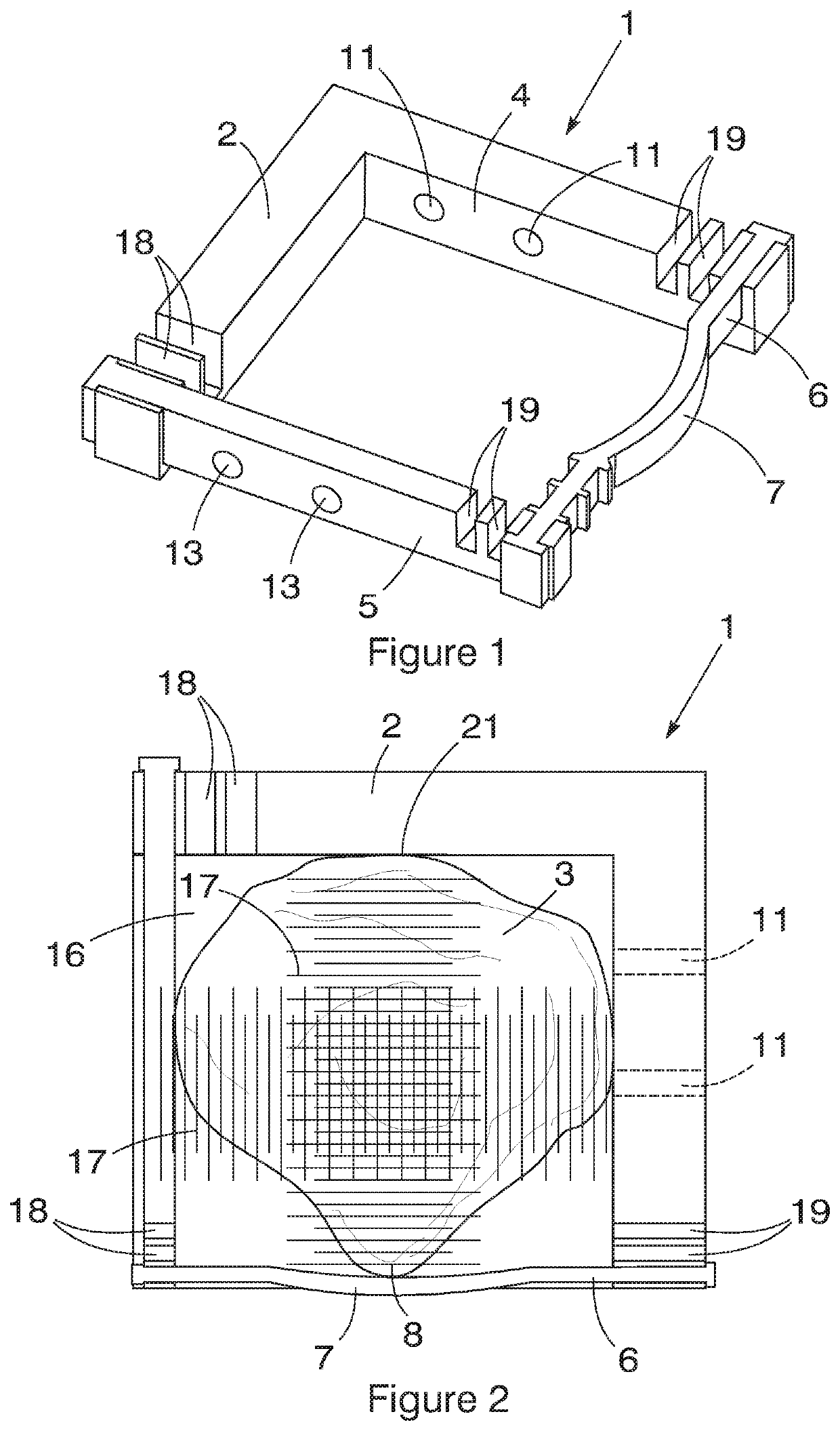
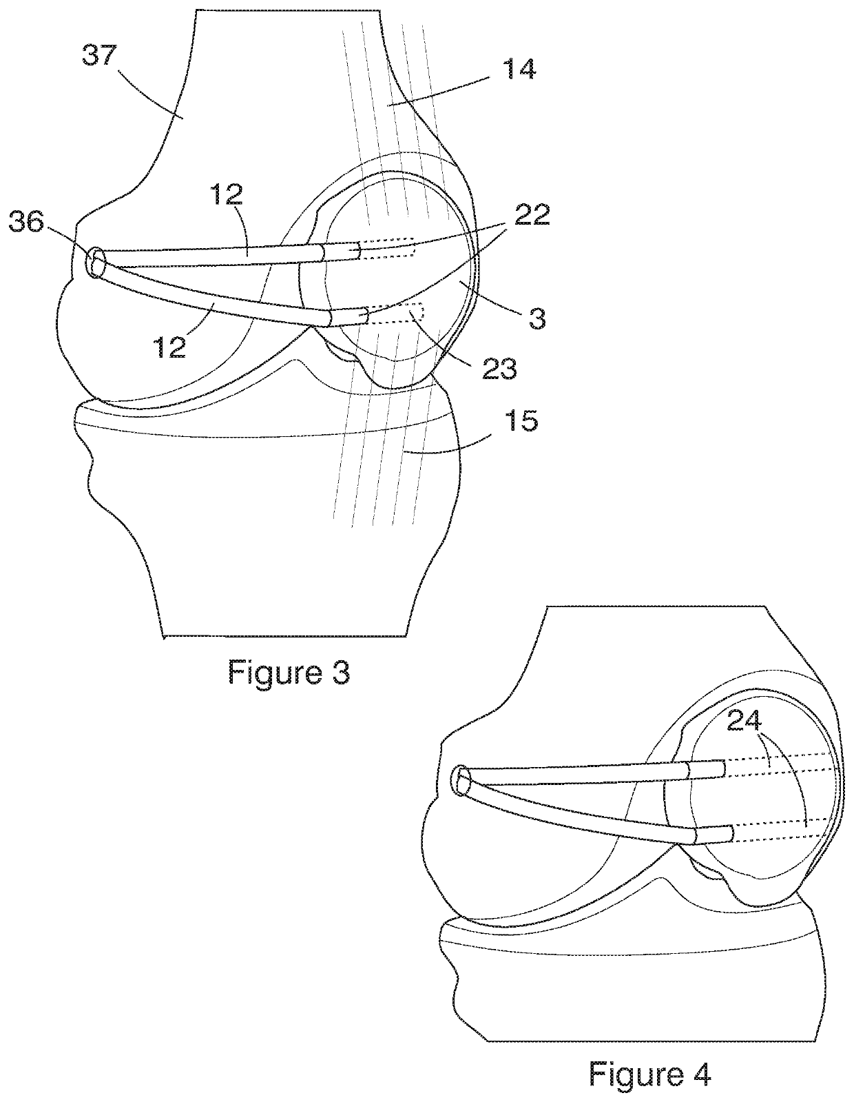
[0011]Further features of the invention provide for the guide limb to be fixed relative to the datum limb typically at generally right angles to the datum limb; for there to be two spaced parallel guide holes extending at generally right angles to the length of the guide limb so as to direct a drill in a direction at generally right angles to the direction in which an associated quadriceps tendon and patellar tendon extend; for the guide holes to be provided in an insert received in a recess in the guide limb in a selected one of a plurality of different positions along a part of the length of the guide limb; for the insert to have along one edge thereof formations and co-operating with a series of co-operating formations, typically in the form of an integral toothed arrangement extending along one longitudinal edge of the recess; for the insert to have two holes of the same diameter one or both of which optionally receive a removable sleeve for providing an alternative smaller diameter hole through the insert with a preferred interaction between the sleeve and larger diameter hole or insert to inhibit rotation of the sleeve within the larger diameter hole; for an upper hole of the guide holes to be spaced from the superior pole of the patella by a distance that is typically of the order of 8 to 12 mm and commonly about 10 mm with a lower guide hole being spaced from the upper guide hole by a distance in the range of from 10 to 18 mm and typically 12 to 15 mm and especially either 12 or 15 mm depending on the physical configuration of the relevant patella; for the surfaces or edges of the datum limb and guide limb to be provided with recesses or protrusions for cooperation with undulations on the edges of a patella; and for the datum limb and guide limb to mutually support an optionally removable scale panel having guide lines or graduations thereon for assisting a surgeon in estimating a direction at right angles to the guide limb for directing a drill and also for assisting in the assessment of the depth of a hole or tunnel being formed in a patella, the scale panel preferably being transparent.
[0013]Still further features of the invention provide for the accessory to have an optionally flexible indicator extending from the guide limb in a direction indicating the direction in which reconstructive ligaments should extend in the final reconstruction towards an attachment point in the femur so as to indicate to a surgeon the line in which reconstructive ligaments should extend so as to avoid difficulties consequent on an incorrect direction that can result from erroneous attachment positions. This indicator assists in determining the point between the adductor tubercle and medial epicondyle of the femur to which it is desired to make the attachment. The accessory, which can be fitted to a normal patella of any size, can be adjusted to determine the medial patella femoral ligament attachment site on the patella.

Problems solved by technology

All acute dislocations cause some degree of macroscopic medial patella femoral ligament damage and studies have shown that lateral dislocation invariably results in at least some damage to the medial patella femoral ligament.
Unfortunately, such an x-ray based procedure is accompanied by a high risk of radiation exposure to the patient, the surgeon, any medical assistants as well as other technical staff.
Non-anatomic reconstruction of the medial patella femoral ligament can lead to non-physiologic patella-femoral loads and kinematics.

Method used


Image

  • Accessory for conducting patella surgery
  • Accessory for conducting patella surgery
  • Accessory for conducting patella surgery

Examples


Embodiment Construction

[0037]Referring to FIGS. 1 to 4 of the drawings, a basic form of accessory (1) for use in the conduct of patella reconstruction surgery, has an elongate datum limb (2) for abutment in use with the top of a patella (3) through the skin and an elongate guide limb (4) extending at right angles to the datum limb for abutment with a side edge of a patella.

[0038]A lateral attachment limb (5) is spaced from, and extends generally parallel to, the guide limb and a transverse attachment limb (6) is spaced from, and extends generally parallel to, the datum limb to form a rectangular aperture. Each of the lateral attachment limb and transverse attachment limb are adjustable in position relative to the datum limb and guide limb so as to form generally rectangular apertures of different sizes in which a particular size of patella can be fitted. The transverse attachment limb may have a downwardly curved shape (7) in a central region to accommodate the lowermost apex (8) of a patella as will be q...


PUM


Abstract

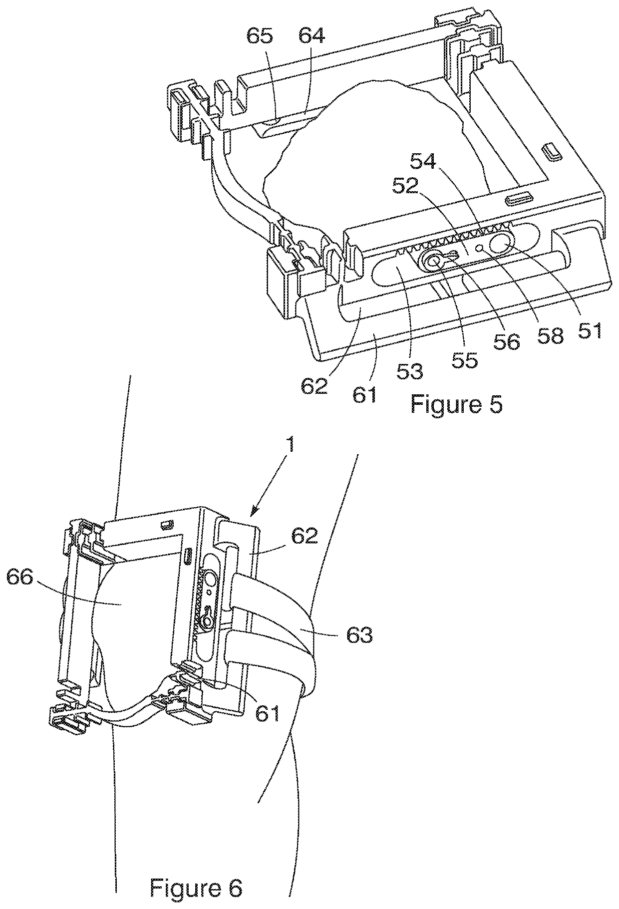
An accessory is provided for use in the conduct of patella reconstruction surgery. The accessory comprises an elongate datum limb for abutment in use with the superior pole of a patella preferably through the skin. An elongate guide limb for abutment by a side edge of a patella extends transversely relative to the datum limb has guide holes passing through it or an insert carried by it at positions selected to direct a drill or other surgical tool at an edge of the patella to enable holes or tunnels to be formed in the patella at required positions for the attachment or reception of reconstructive ligaments to the patella. Attachment limbs enable the accessory to be secured in an operative position relative to a patella. There may be slots formed by anchor bars integral with the guide limb and attachment limb to strap the accessory to a patient's knee.

Description

CROSS-REFERENCE TO RELATED APPLICATIONS[0001]The present invention is a 35 U.S.C. § 371 U.S. National Stage Application corresponding to PCT Application No. PCT / IB2016 / 053967, filed on Jul. 1, 2016, which claims priority to U.K. Application No. 1511597.5, filed Jul. 2, 2015. The entire content of each of the aforementioned patent applications is incorporated herein by reference.FIELD OF THE INVENTION[0002]This invention relates to an accessory for conducting patella surgery and, in particular, an accessory that is aimed at assisting a surgeon in forming attachment holes or tunnels in the patella during medial patella femoral ligament reconstruction.BACKGROUND TO THE INVENTION[0003]Patella dislocation is one of the most common pathologies of the knee joint. The medial patella femoral ligament plays a pivotal role in the avoidance of patella-femoral instability. Rupturing of the medial patella femoral ligament is the main pathological consequence of patellar dislocation. All acute dis...

Claims


Application Information

Patent Timeline
Patent Type & Authority Patents(United States)
IPC IPC(8): A61B17/17A61B17/00A61B90/00
CPCA61B17/1714A61B17/1767A61B2090/3983A61B2017/00991A61B2017/0023A61B2090/067A61B2090/062A61B17/17
Inventor PATNAIK, SARTHAKSIVARASU, SUDESH
Owner PATNAIK SARTHAK
Learn More