Method of determining a calibration or maintenance time interval

Active Publication Date: 2020-01-21
ENDRESSHAUSER GRP SERVICES AG
View PDF0 Cites 1 Cited by
  • Summary
  • Abstract
  • Description
  • Claims
  • Application Information

AI Technical Summary

Benefits of technology

[0015]It is an object of the invention to provide a method of determining a calibration time interval or a maintenance time interval after which a specific measurement device of a given type f

Problems solved by technology

Thus measurement devices play a vital part in industrial processes, and a defect of a device may have severe consequences.
Industrial production sites are quite often very complex sites including a large number of measurement devices on various measurement sites.
Based on the measurement results obtained by the device with respect to the given value of the quantity to be measured, a measurement error of the device is determined.
In case the measurement error exceeds a predetermined maximum permissible error, the device is considered not to conform.
Short calibration time intervals raise the costs involved in operating these devices.
Determination of the reliability function however, requires a large amount of so called historical data.
This method can only be applied, when sufficient historical data is available for the type of measureme

Method used


Image

  • Method of determining a calibration or maintenance time interval
  • Method of determining a calibration or maintenance time interval
  • Method of determining a calibration or maintenance time interval

Examples


Example

DETAILED DISCUSSION IN CONJUNCTION WITH THE DRAWINGS

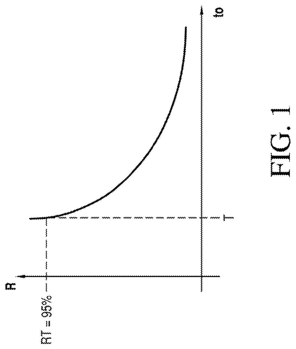
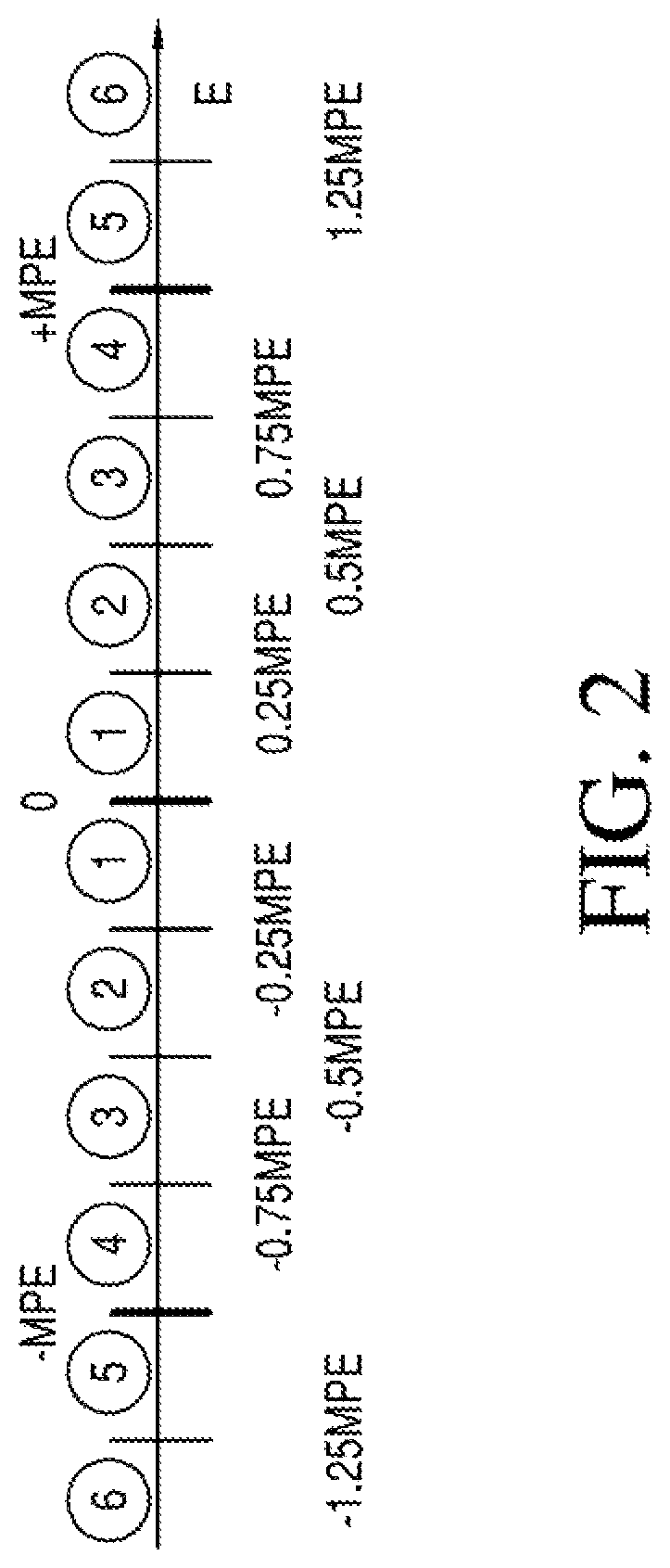
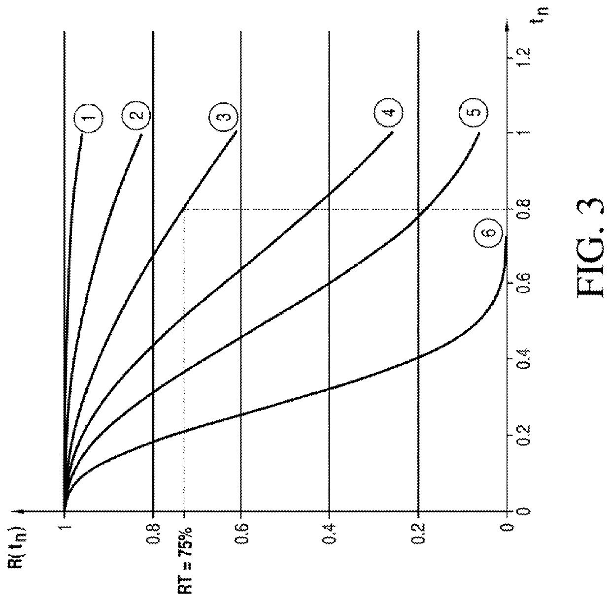
[0068]The invention provides a method of determining a calibration time interval after which a specific measurement device of a given type for measuring a quantity to be measured operating on a measurement site of an industrial site shall be re-calibrated.

[0069]The measurement device can be any type of measurement device available on the market, like for example a level measurement device for measuring a level of a product in a container, a flow meter for measuring a flow of a product through a pipe, a temperature measurement device or a pressure measurement device. Corresponding to the measurement device, the measurement site can for example be a production hall, any type of container or vessel or a pipe. The industrial site is for example a laboratory, a production plant, a refinery or a steel furnace.

[0070]The method comprises a first step of determining a criticality C of the specific device. Criticality assessment can be perfo...


PUM


Abstract

A method of determining a calibration or maintenance time interval, comprising the steps of: determining a criticality of the specific device, based on the criticality setting a reliability target for the device, wherein the reliability target denominates the probability of the device to be compliant according to a predefined criterion at the end of the calibration or maintenance time interval; defining compliancy ranges for a measurable degree of compliance of the device; selecting a reliability model for a reliability of the device as a function of a normalized time interval and a set of at least one parameter from a variety of predefined reliability models, determining a separate set of parameters for the selected reliability model for each of the compliancy ranges based on prescribed reliability expectation values for each of the error ranges, which a reliability function associated with this error range shall comply to at at least one predefined normalized time, determining the degree of compliance of the specific measurement device and based on the degree of compliance determining the corresponding compliancy range; determining a normalized calibration or maintenance time as the time, at which a reliability function given by the selected reliability model and the set of parameters determined for this compliancy range equals the reliability target; and determining the next calibration or maintenance time interval based on a product of this normalized calibration or maintenance time and a given reference time interval.

Description

TECHNICAL FIELD[0001]The present invention relates to a method of determining a calibration time interval or a maintenance time interval after which a specific measurement device of a given type for measuring a quantity to be measured operating on a measurement site of an industrial site shall be calibrated or maintained.[0002]The present invention concerns a method of determining a calibration time interval or a maintenance time interval after which a specific measurement device of a given type for measuring a quantity to be measured operating on a measurement site of an industrial site shall be calibrated or maintained.BACKGROUND DISCUSSION[0003]Measurement devices are used in nearly all branches of industry for measuring quantities, in particular physical quantities related to ongoing production processes. Measurement results indicating the measured value of the quantity are for example commonly used in process automation for monitoring, controlling and / or regulating an industria...

Claims


Application Information

Patent Timeline
IPC IPC(8): G04F13/00G01D18/00
CPCG04F13/00G01D18/006
Inventor VAISSIERE, DIMITRI
Owner ENDRESSHAUSER GRP SERVICES AG
Why Eureka
Try Eureka