Article storage facility

a technology for storage facilities and articles, applied in storage devices, electrical devices, transportation and packaging, etc., can solve the problems of less easily transmitting vibrations from one of the first rails, and less easily transmitting vibrations caused by one of the transport devices to the other of the transport devices, so as to achieve the effect of less easily transmitting

Active Publication Date: 2020-03-10
DAIFUKU CO LTD
View PDF5 Cites 0 Cited by
  • Summary
  • Abstract
  • Description
  • Claims
  • Application Information

AI Technical Summary

Benefits of technology

[0006]In light of this issue, an article storage facility is desired in which vibrations from one of the transport devices are less easily transmitted to another.
[0008]With the arrangement described above, the third rail is located between the first rail and second rail which are located to be spaced apart, by the set distance, from each other along the rail extending direction. This third rail includes a fixed base whose location is fixed with respect to the first rail and the second rail and a movable rail portion whose location with respect to the fixed base when fixed thereto can be changed. Because the length of the third rail along the rail extending direction is less than the set distance, a gap is formed between the movable rail portion and the first rail or the second rail. Therefore, vibrations are less easily transmitted from one of the first rail and the second rail to the other of the first rail and the second rail, through the third rail. In other words, vibrations caused by one of the transport devices are less easily transmitted to the other of the transport devices.

Problems solved by technology

Therefore, vibrations are less easily transmitted from one of the first rail and the second rail to the other of the first rail and the second rail, through the third rail.
In other words, vibrations caused by one of the transport devices are less easily transmitted to the other of the transport devices.

Method used


Image

  • Article storage facility
  • Article storage facility
  • Article storage facility

Examples


Embodiment Construction

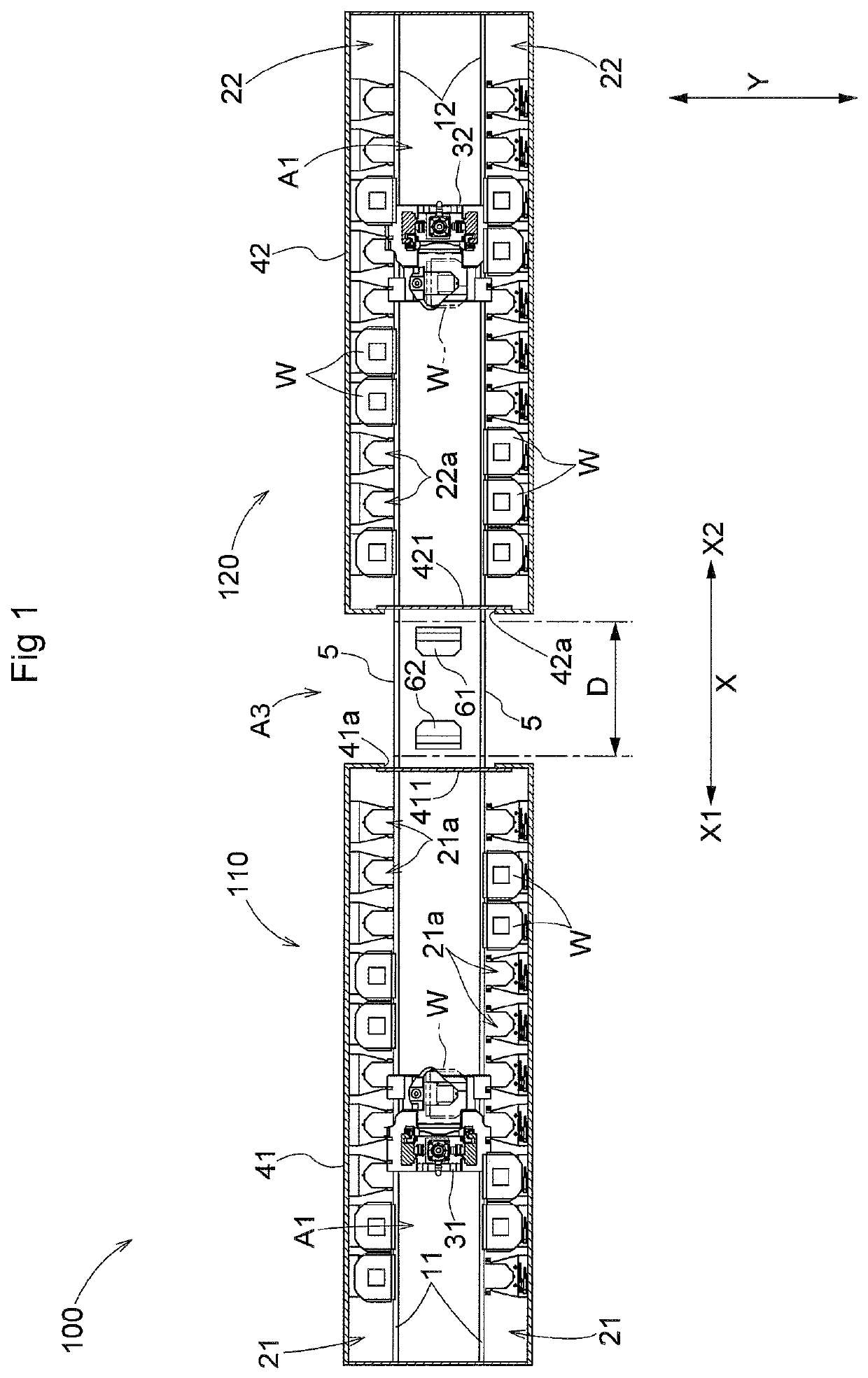
[0018]A article storage facility 100 in accordance with an embodiment is described with reference to the attached drawings. As shown in FIG. 1, the article storage facility 100 includes a first stocker 110 and a second stocker 120.

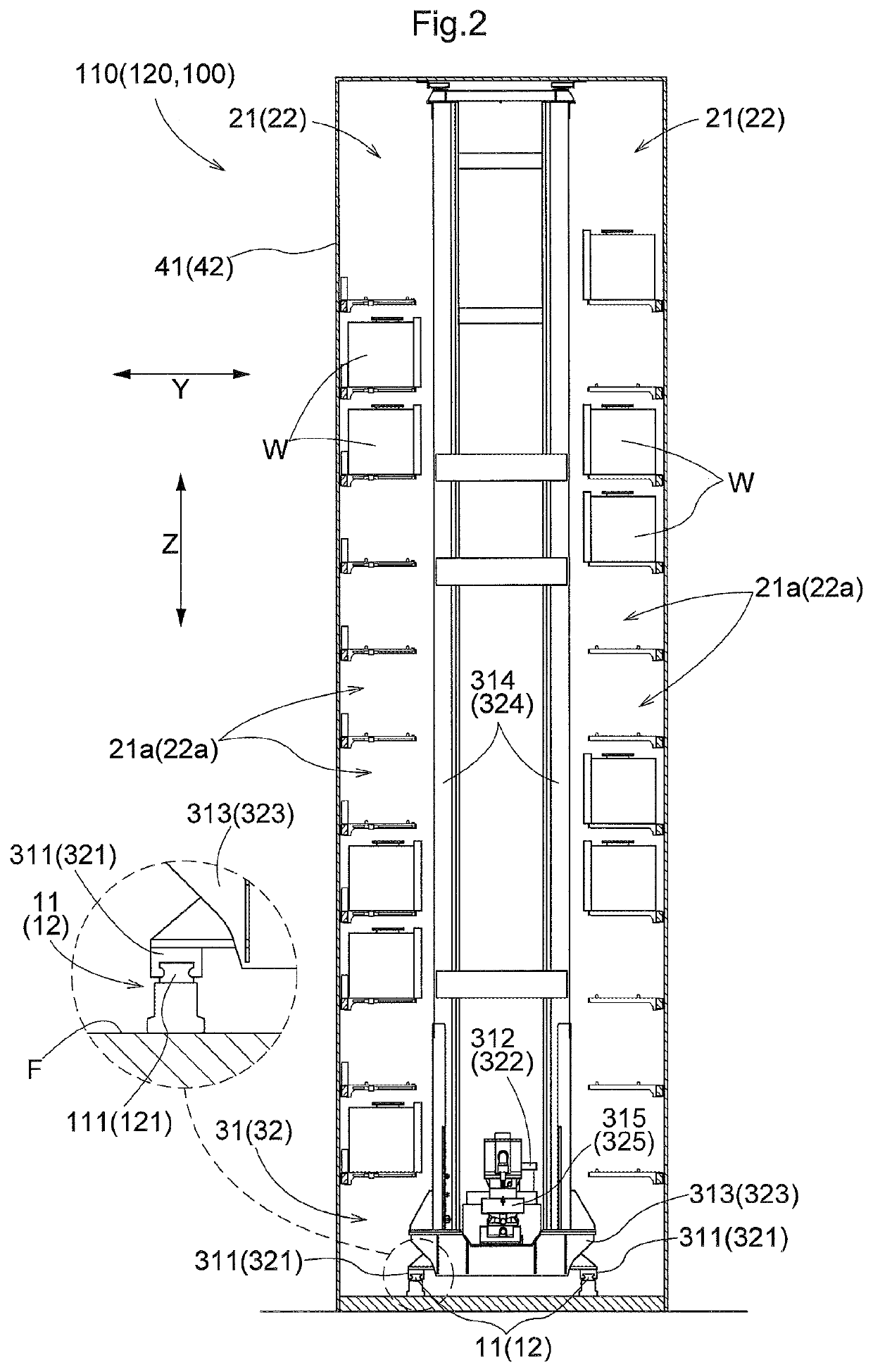
[0019]As shown in FIGS. 1 and 2, the first stocker 110 includes first rails 11 extending along a rail extending direction, first storage racks 21 each of which is disposed to extend along the first rails 11 and is configured to store a plurality of articles W, and a first transport device 31 configured to move along the first rails 11 and to transfer an article W to and from either of the first storage racks 21. Note that, in the present embodiment, each article W is a container (more specifically, a FOUP (Front Opening Unified Pod)) which is configured to hold one or more semiconductor substrates.

[0020]In the following description, the rail extending direction of the first rails 11 (the direction along which the first rails 11 extend) will be referred to ...


PUM


Abstract

An article storage facility includes a first rail extending along a rail extending direction, a first storage rack configured to store a plurality of articles, a first transport device configured to move along the first rail and to transfer an article to and from the first storage rack, a second rail extending along the rail extending direction; and a second storage rack configured to store a plurality of articles, and a second transport device configured to move along the second rail and to transfer an article to and from the second storage rack. The first rail and the second rail are spaced apart by a set distance from each other along the rail extending direction. A third rail extends along the rail extending direction between the first rail and the second rail, and has a length less than the set distance. The third rail includes a fixed base and a movable rail portion. The movable rail portion is so configured that a location of the movable rail portion with respect to the fixed base when fixed to the fixed base can be changed.

Description

FIELD OF THE INVENTION[0001]The present invention relates to an article storage facility comprising a first rail extending along a rail extending direction, a first storage rack extending along the first rail and configured to store a plurality of articles, a first transport device configured to move along the first rail and to transfer an article to and from the first storage rack, a second rail extending along the rail extending direction as in the case of the first rail, a second storage rack extending along the second rail and configured to store a plurality of articles, and a second transport device configured to move along the second rail and to transfer an article to and from the second storage rack.BACKGROUND ART[0002]An example of such an article storage facility is disclosed in JP Publication of Application No. 2015-9953 (Patent Document 1). In the following description of this background art section, the names of the parts and the reference numerals used in Patent Documen...

Claims


Application Information

Patent Timeline
Patent Type & Authority Patents(United States)
IPC IPC(8): B65G1/137
CPCB65G1/1373H01L21/67769
Inventor KAWAMURA, SHINSUKE
Owner DAIFUKU CO LTD
Why Eureka
Try Eureka