Electret Condenser Microphone

a condenser microphone and condenser technology, applied in the direction of deaf-aid sets, electrical transducers, electrical equipment, etc., can solve the problems of disadvantageous deformation of the top surface of the capsule, difficult to maintain a predetermined posture of the ecm, and adverse effects on parts housed in the capsul

Inactive Publication Date: 2011-01-20
HOSIDEN CORP
View PDF11 Cites 9 Cited by
  • Summary
  • Abstract
  • Description
  • Claims
  • Application Information

AI Technical Summary

Benefits of technology

[0014]With the above-noted arrangement, the cap member is provided between the capsule and the capacitor section. Thus, even if the capsule is heated, the heat is alleviated by the cap member and less easily transmitted to the capacitor section. As a result, the capacitor section housed in the capsule is prevented from being deteriorated. In particular, the heat influence exerted on the electret layer provided in the capacitor section can be suppressed, which can prevent deterioration of the polarization of the electret layer caused by the heat.
[0027]In addition, even if the suction nozzle of the transporting device is brought into contact with a position deviated from the suctioned portion, the suction nozzle would never seal the acoustic hole, which can prevent the diaphragm or the back electrode plate housed in the capsule from being damaged.

Problems solved by technology

When the conventional ECM is transported in the reflow mounting process, the portion other than the acoustic hole that is deviated from the center of gravity is drawn to transport the ECM, as a result of which it is sometimes difficult to maintain a predetermined posture of the ECM during the transportation.
On the other hand, when a drawing force of the transporting device is increased in an attempt to solve the above problem, the top surface of the capsule is disadvantageously deformed, for example, which leaves room for improvement.
In that case, the parts housed in the capsule may be adversely affected by the heat.
In addition, cooling air for cooling the capsule enters the capsule through the acoustic hole formed in the top surface of the capsule to possibly exert an adverse influence on the parts housed in the capsule.
For instance, the diaphragm may be slackened by heated air or cooling air, or polarization of the electret layer may be deteriorated by the heat.
Nonetheless, the conventional ECM has not adopted any effective measure to counter the heat transmission to the inner parts from heated air, cooling air or the capsule as noted above which possibly creates the problem in the reflow mounting process.

Method used


Image

  • Electret Condenser Microphone
  • Electret Condenser Microphone
  • Electret Condenser Microphone

Examples


Embodiment Construction

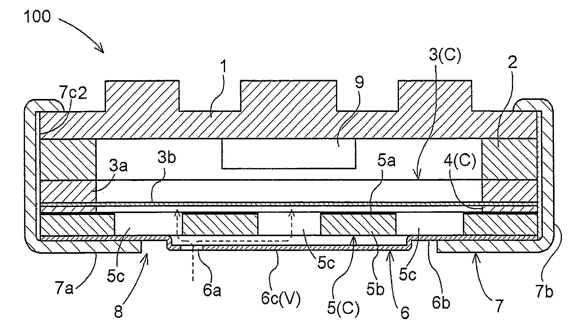
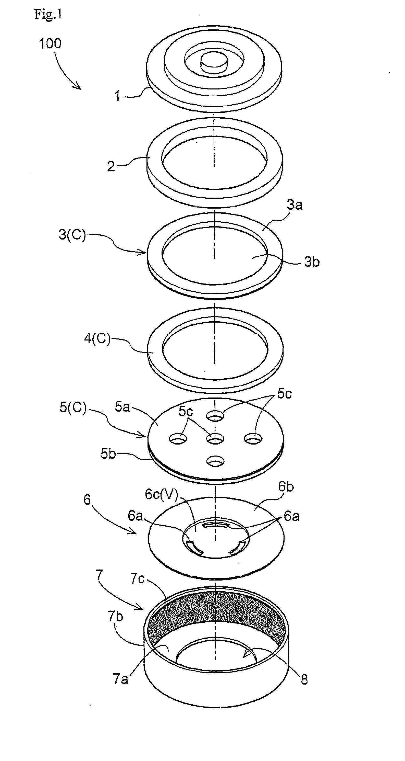
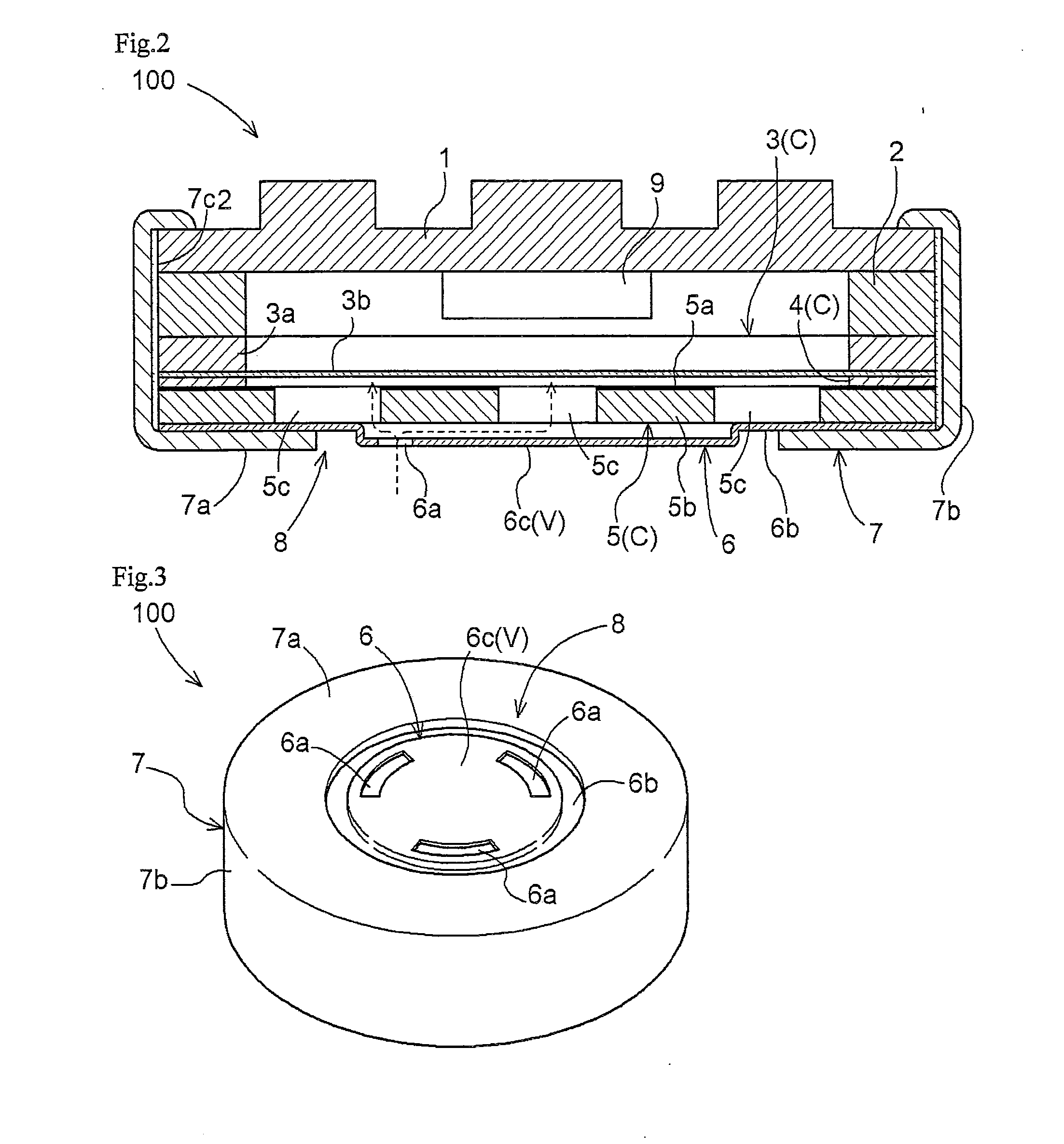
[0034]An electret condenser microphone (referred to as an “ECM” hereinafter) of the present invention will be described hereinafter in reference to the accompanying drawings. FIG. 1 is an exploded perspective view of the ECM100, and FIG. 2 is a sectional view of the ECM100.

[0035]As shown in FIGS. 1 and 2, the ECM100 comprises a capsule 7 consisting of a cylindrical side member 7b and a top member 7a, which includes various elements therein. Inside of the capsule 7 are housed, from the side of the top member 7a, a cap member 6, a back electrode plate 5, a spacer ring 4, a diaphragm 3, a gate ring 2, and a substrate 1. The side member 7b of the capsule 7 is crimped at their ends to hold the substrate 1 therein thereby fixing the various elements within the capsule 7. The capsule 7 is made of a conductive material such as metal.

[0036]In the current embodiment, the cylindrical capsule 7 will be described, while the shape of the capsule 7 may be a rectangular tube.

[0037]In the current em...


PUM


Abstract

An electret condenser microphone includes a conductive capsule including an opening formed in a top member, a capacitor section including a diaphragm, a back electrode plate arranged to face either surface of the diaphragm, and a electret layer provided on the diaphragm or the back electrode plate, which are housed in the capsule, and a cap member provided between the capacitor section and the top member of the capsule and including an acoustic hole formed in a portion exposed to the outside through the opening, wherein the cap member further includes a suctioned portion formed in a central portion thereof to be drawn by a suction-type transporting device, the acoustic holes being arranged along the circumference of the suctioned portion.

Description

TECHNICAL FIELD[0001]The present invention relates to an electret condenser microphone (referred to as an “ECM” hereinafter) comprising a capacitor section including a diaphragm, a back electrode plate arranged to face either surface of the diaphragm, and a electret layer provided on the diaphragm or the back electrode plate, all of which are housed in a capsule.BACKGROUND ART[0002]The ECM has been applied to a wide variety of electronic devices such as a mobile phone, a PDA and a digital camera, for example. The ECM is a minute element and mounted on each of the devices using surface mounting technology. For example, the reflow mounting technique is used in which solder is applied on a wiring substrate to mount the ECM thereon, and then the substrate is heated and soldered. In order to speed up in mounting the ECM on the wiring substrate, the reflow mounting process sometimes uses a suction-type transporting device to transport the ECM to the wiring substrate.[0003]Many of the conv...

Claims


Application Information

Patent Timeline
Patent Type & Authority Applications(United States)
IPC IPC(8): H04R25/00
CPCH04R19/016
Inventor IZUCHI, TOSHIRONAKANISHI, KENSUKEBABA, TSUYOSHI
Owner HOSIDEN CORP
Why Eureka
Try Eureka