Hammer drill adaptors and methods of use

a technology for adaptors and hammer drills, applied in the field of adaptors for hammer drills, can solve the problems of bent drive cleats and shoulder injuries, and achieve the effects of reducing the risk of injury

Active Publication Date: 2020-03-17
AHO RONALD
View PDF42 Cites 49 Cited by
  • Summary
  • Abstract
  • Description
  • Claims
  • Application Information

AI Technical Summary

Benefits of technology

[0006]Hammer drills are known in the art and configured to perform a hammering action. Hammer drills, also known as a rotary hammers or hammering drills are a rotary drill with a hammering action. The hammering action is typically used to provide a short, rapid hammer thrust to pulverize relatively brittle material and provide quicker drilling with less effort. These tools are usually electrically powered, and increasingly powered by two batteries. Disclosed are novel adaptors for use within hammer drills and configured for coupling with a drive cleat whereby the powered action of the hammer drill is transferred through a novel drive cleat adaptor to drive a drive cleat for simplified and safe duct connection.
[0008]In one form, a hammer drill adaptor enables a user to use a hammer drill, instead of a common hammer, to install a drive cleat thereby saving time and effort and injury during installation.
[0058]In one form, a drive cleat adaptor comprises a drive cleat retension member. A drive cleat retension member adds the additional functional benefit of releasably holding a drive cleat in a capture cavity thereby preventing unintentional drop out of the drive cleat from a capture cavity if the user tilts the hammer drill to the side or downwards for any reason.
[0064]In one form, an elongate spring channel may be formed in a cover portion to house a spring end thereby preventing interference between a drive cleat and the spring end during drive cleat insertion into a capture cavity.
[0079]In one form, a method of using a hammer drill adaptor to install a drive cleat to join air ducts comprises the steps of: obtaining a drive cleat suited to join two adjacent air ducts along a seam; obtaining a hammer drill having a hammer drill chuck; obtaining a hammer drill adapter having a shaft portion and a first portion where said shaft portion extends from said first portion and wherein said first portion has a generally rectangular shaped capture cavity extending proximally from a distal end of said hammer drill adaptor and wherein said capture cavity terminates at a rear surface; securing of portion of said shaft portion of the hammer drill adapter in the hammer drill chuck; engaging the hammer drill chuck within one or more of a first and second connection portion of a hammer drill adaptor; inserting a trailing end of said drive cleat into said capture cavity until a terminal end of the drive cleat abuts said rear surface of said drive cleat at a proximal end of said capture cavity; positioning the hammer drill with drive cleat seated in the capture cavity to a seam of adjacent air ducts; joining the leading end of the drive cleat to a seam joining a first duct and second duct; actuating the hammer drill to exert a plurality of pulses; advancing said hammer drill adapter by application of a force generally along a central axis of said shaft portion thereby driving said drive cleat into an installed position wherein the drive cleat joins together the first and second duct. A next step comprises withdrawing said hammer drill adaptor, hammer drill chuck, and hammer drill from said drive cleat after the drive cleat is in an installed position. In the event the drive cleat requires to be driven further, a next step comprises the step of removing the drive cleat from the capture cavity and repositioning it approximately 90 degrees within a slot extending through an upper surface and an upper capture surface of said hammer drill adaptor. The user then finishes installation of the drive cleat to further push the drive cleat into a fully installed position. Again, if further driving of the drive cleat is required, the user may position an entry surface at a distal end of a first portion of the adapter against the trailing end of the drive cleat so as to exert a force against the distal end of the drive cleat. This step provides the user a method to gently tap the drive cleat into a final installed position.

Problems solved by technology

However, this method is time consuming, difficult to maneuver and may lead to bent drive cleats during the installation process.
In addition, this repetitive manual impact motion is known to cause shoulder injuries.

Method used


Image

  • Hammer drill adaptors and methods of use
  • Hammer drill adaptors and methods of use
  • Hammer drill adaptors and methods of use

Examples


Embodiment Construction

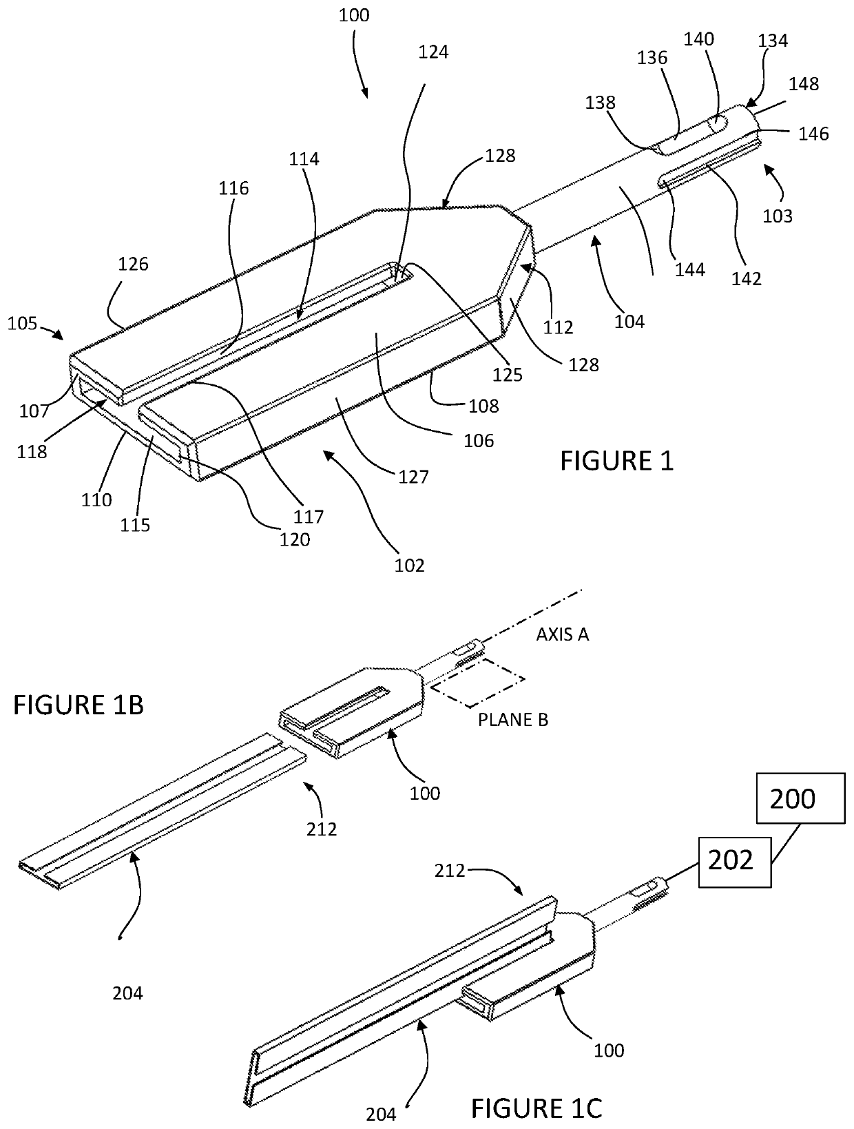
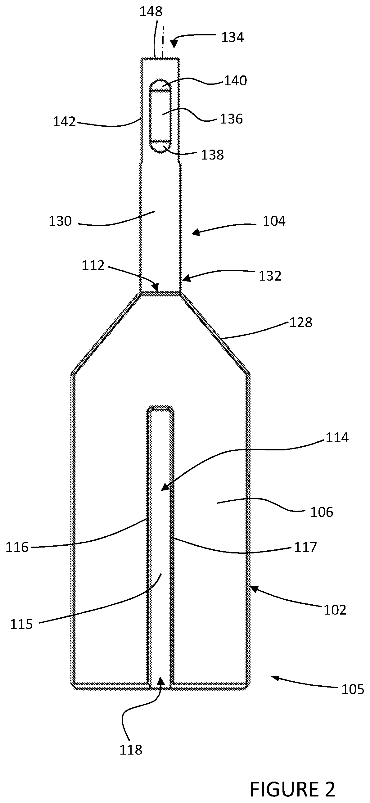
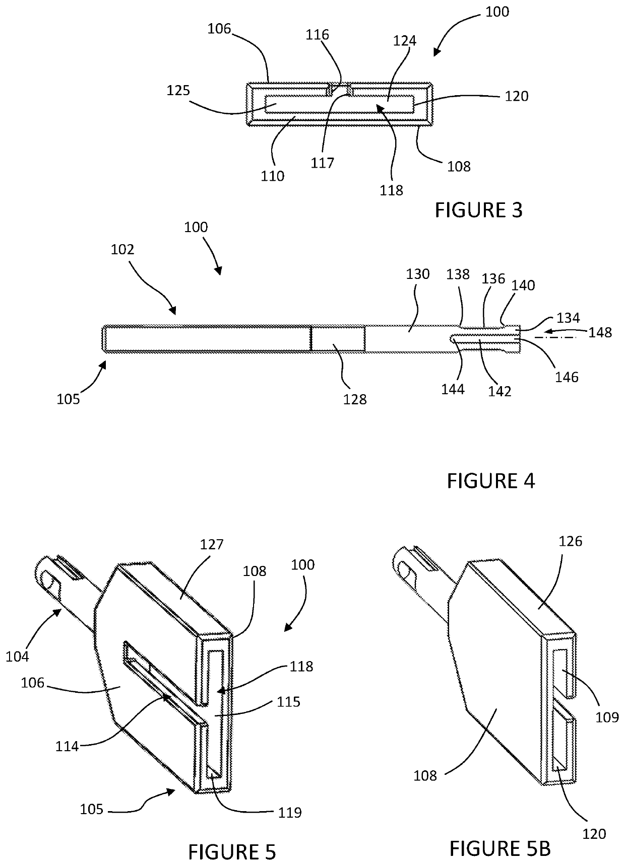
[0111]Select embodiments of the invention will now be described with reference to the Figures, wherein like numerals reflect like elements throughout. Various depicted embodiments having like numerals are distinguished using a letter in addition to the numeral. The terminology used in the description presented herein is not intended to be interpreted in any limited or restrictive way, simply because it is being utilized in conjunction with detailed description of certain specific embodiments of the invention. Furthermore, embodiments of the invention may include several novel features, no single one of which is solely responsible for its desirable attributes or which is essential to practicing the invention described herein.

[0112]In one embodiment (FIGS. 1-7), an adaptor is configured to be releasably fixed to a standard hammer drill at one end and to releasably hold a standard drive cleat at an opposing end. The adaptor enables a user to use a hammer drill, instead of a common hamm...


PUM


Abstract

A hammer drill adapter for driving a drive cleat to join opposed ends of a duct comprising: a first portion generally aligned in a plane; a shaft portion having an elongate axis generally parallel to said plane; the first portion fixed to the shaft portion; an entry surface at a distal end of the first portion; a capture cavity extending through the entry surface; the capture cavity defined proximally by a rear surface and by an opposed lower and upper capture surfaces; the capture cavity also laterally defined by an opposed first capture surface and a second capture surface; the capture cavity sized to house a trailing end portion of a drive cleat; and wherein the shaft portion comprises a connection portion at a proximal end of said shaft portion for fixation within a hammer drill chuck. Also disclosed are methods for use to advance a drive cleat.

Description

CROSS REFERENCE TO RELATED APPLICATIONS[0001]This application claims priority to Provisional Patent Application No. 62 / 373,466 filed Aug. 11, 2016, the entire disclosure of which is hereby incorporated by reference and relied upon.BACKGROUND OF THE INVENTIONField of the Invention[0002]The invention relates generally to adaptors for use in hammer drills, and more particularly to hammer drill adaptors and their methods of use for driving a drive cleat to join together air ducts at a seam.Description of Related Art[0003]In HVAC and other air flow systems, both the air ducts and drive cleats are typically galvanized steel and / or aluminum in construction. Drive cleats are used to join sections of rectangular ducts in HVAC and other air flow systems. Ducts are configured to have a lip, indentation or other bracket to connect the drive cleat to the ducts.[0004]A common handheld hammer is used to impact a drive cleat to connect air ducts together. Since air ducts are typically overhead, she...

Claims


Application Information

Patent Timeline
Patent Type & Authority Patents(United States)
IPC IPC(8): B25D17/02B25D17/08
CPCB25D17/08B25D17/02B25D2217/0003B25D2250/141B25D17/005B25D2217/0007
Inventor AHO, RONALD
Owner AHO RONALD
Why Eureka
Try Eureka