Image forming apparatus
a technology of forming apparatus and forming tube, which is applied in the direction of electrographic process apparatus, instruments, optics, etc., can solve the problems of non-uniformity generation of images, varying degree of influence of expansion and contraction of images on image non-uniformity, and density non-uniformity in some instances, so as to suppress expansion and contraction of image generating
- Summary
- Abstract
- Description
- Claims
- Application Information
AI Technical Summary
Benefits of technology
Problems solved by technology
Method used
Image
Examples
embodiment 1
(Image Forming Apparatus)
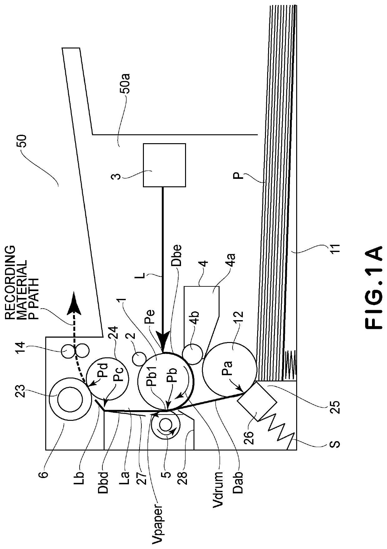
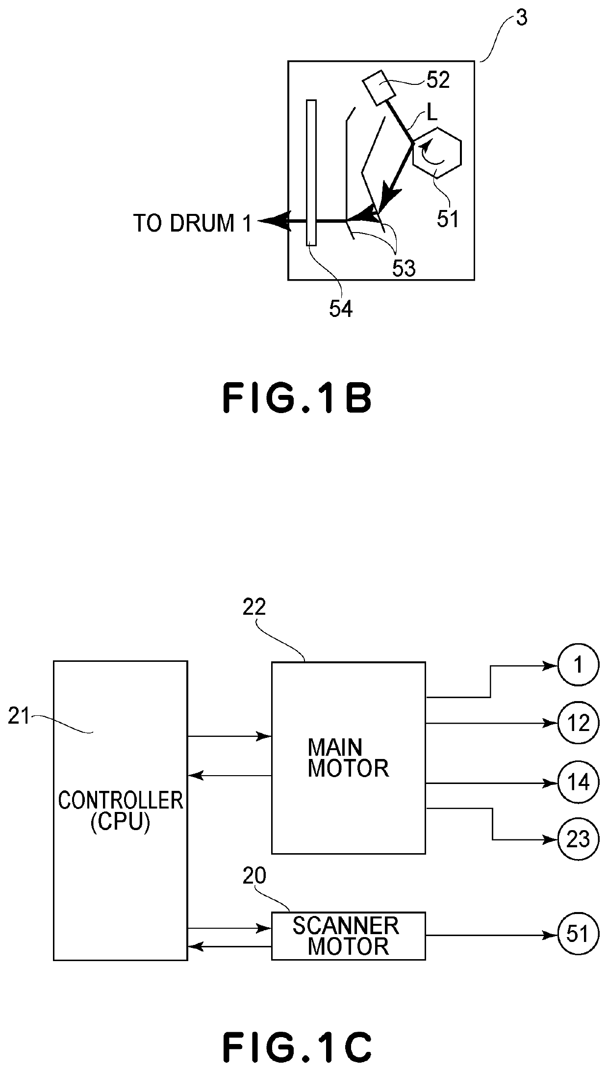
[0049]FIG. 1A is a sectional view showing a schematic structure of an example of an image forming apparatus (monochromatic printer in this embodiment) 50 using electrophotographic recording. FIG. 1B is a plan view showing a schematic structure of an exposure portion 3. FIG. 1C is a block diagram showing a driving system of a main motor 22 and a scanner motor 20.
[0050]The structure of the image forming apparatus in this embodiment will be described with reference to FIGS. 1A to 1C. In FIG. 1A, a broken line represents a feeding path of a recording material P (recording material P feeding path).
[0051]A photosensitive drum (image bearing member) 1 is rotated by driving the main motor 22 (FIG. 1C) by a control device (CPU) 21 effecting drive control of an image forming apparatus 50. An outer diameter of the photosensitive drum 1 is 20 mm. At a normal driving speed of the main motor 22, a moving speed (process speed) Vdrum of an outer peripheral surface of the ph...
embodiment 2
[0140]Another embodiment of the image forming apparatus 50 will be described. A feature of the image forming apparatus 50 in this embodiment is that double-side printing can be carried out using a reversing mechanism (reversing portion) 17 for turning the recording material P upside down and that the change in surface movement speed of the photosensitive drum 1 is different between the first side and the second side.
[0141]In the following, the structure of the image forming apparatus 50 will be described with reference to FIG. 7. In FIG. 7, (a) is a sectional view showing a schematic structure of the image forming apparatus 50 in this embodiment, and (b) is a block diagram showing a driving system of a main motor 22 and a scanner movement 20.
[0142]In this embodiment, members which are the same as those in Embodiment 1 are represented by the same reference numerals or symbols and will be omitted from description.
[0143]The reversing mechanism 17 includes an introducing guide 18 provid...
embodiment 3
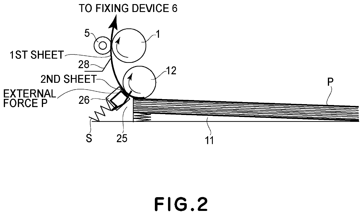
[0163]Another embodiment of the image forming apparatus 50 will be described. The external force exerted on the recording material P in the apparatus main assembly 50a is not limited to the frictional resistance by the separation pad 26 of the sheet feeding portion 25 and the tensile force of the pressing roller 23. In the image forming apparatus 50 in Embodiment 1, after the leading end of the recording material P entered the fixing nip Pd, as the external force, the force was exerted on the recording material P in the direction of pulling the recording material P. For this reason, the apparatus in which the surface movement speed of the photosensitive drum 1 was gradually reduced was described. In this embodiment, an example in which the surface movement speed of the photosensitive drum 1 is increased will be described.
[0164]An image forming apparatus shown in (a) of FIG. 9 has a constitution in which an entrance guide 281 toward the transfer nip Pb entered the photosensitive drum...
PUM
 Abstract
Description
Claims
Application Information
 - R&D
- Intellectual Property
- Life Sciences
- Materials
- Tech Scout
- Unparalleled Data Quality
- Higher Quality Content
- 60% Fewer Hallucinations
Browse by: Latest US Patents, China's latest patents, Technical Efficacy Thesaurus, Application Domain, Technology Topic, Popular Technical Reports.
© 2025 PatSnap. All rights reserved.Legal|Privacy policy|Modern Slavery Act Transparency Statement|Sitemap|About US| Contact US: help@patsnap.com


