Image forming apparatus

a technology of forming apparatus and forming tube, which is applied in the direction of electrographic process apparatus, instruments, optics, etc., can solve the problems of non-uniformity generation of images, varying degree of influence of expansion and contraction of images on image non-uniformity, and density non-uniformity in some instances, so as to suppress expansion and contraction of image generating

Active Publication Date: 2020-07-02
CANON KK
View PDF1 Cites 0 Cited by
  • Summary
  • Abstract
  • Description
  • Claims
  • Application Information

AI Technical Summary

Benefits of technology

The present invention provides an image forming apparatus that can keep the image stable without expanding or contracting due to changes in external force on the recording material. This ensures that the image is output without any density non-uniformity.

Problems solved by technology

When the image density changes, image non-uniformity generates in some cases.
Depending on a difference in resolution, a degree of the influence of the expansion and contraction of the image on the image non-uniformity varies.
For that reason, when the image with the resolution higher than ever is intended to be formed, the density non-uniformity generated in some instances.

Method used


Image

  • Image forming apparatus
  • Image forming apparatus
  • Image forming apparatus

Examples


embodiment 1

(Image Forming Apparatus)

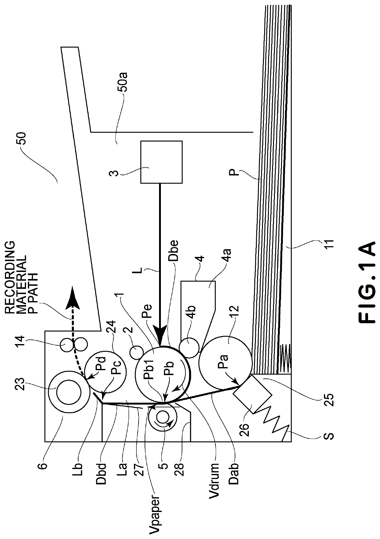
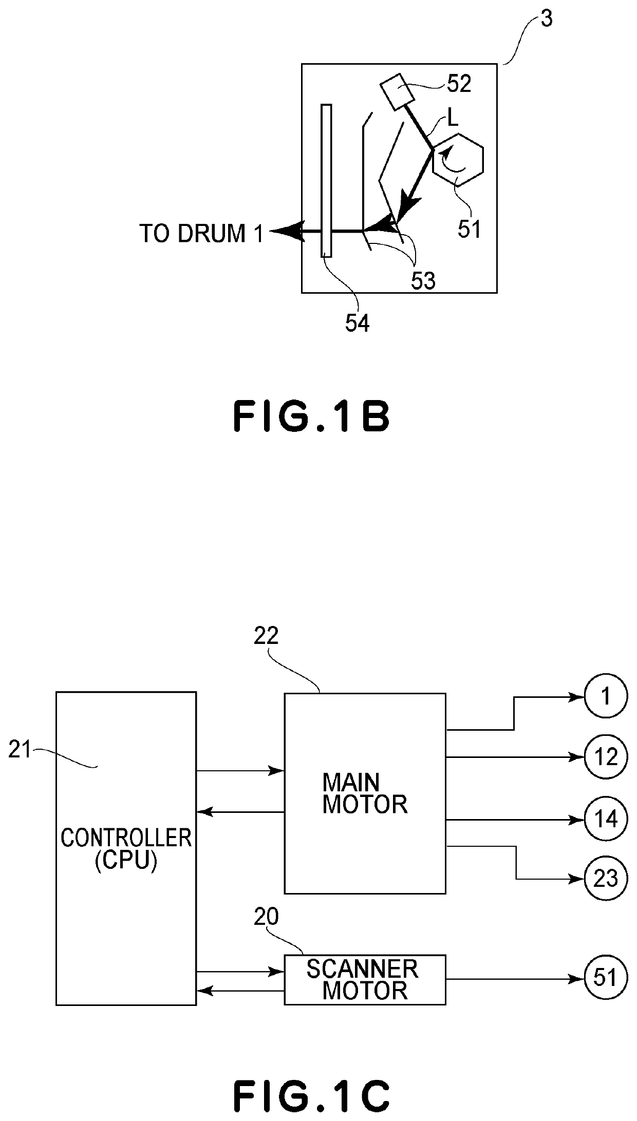
[0049]FIG. 1A is a sectional view showing a schematic structure of an example of an image forming apparatus (monochromatic printer in this embodiment) 50 using electrophotographic recording. FIG. 1B is a plan view showing a schematic structure of an exposure portion 3. FIG. 1C is a block diagram showing a driving system of a main motor 22 and a scanner motor 20.

[0050]The structure of the image forming apparatus in this embodiment will be described with reference to FIGS. 1A to 1C. In FIG. 1A, a broken line represents a feeding path of a recording material P (recording material P feeding path).

[0051]A photosensitive drum (image bearing member) 1 is rotated by driving the main motor 22 (FIG. 1C) by a control device (CPU) 21 effecting drive control of an image forming apparatus 50. An outer diameter of the photosensitive drum 1 is 20 mm. At a normal driving speed of the main motor 22, a moving speed (process speed) Vdrum of an outer peripheral surface of the ph...

embodiment 2

[0138]Another embodiment of the image forming apparatus 50 will be described. A feature of the image forming apparatus 50 in this embodiment is that double-side printing can be carried out using a reversing mechanism (reversing portion) 17 for turning the recording material P upside down and that the change is surface movement speed of the photosensitive drum 1 is different between the first side and the second side.

[0139]In the following, the structure of the image forming apparatus 50 will be described with reference to FIG. 7. In FIG. 7, (a) is a sectional view showing a schematic structure of the image forming apparatus 50 in this embodiment, and (b) is a block diagram showing a driving system of a main motor 22 and a scanner movement 20.

[0140]In this embodiment, members which are the same as those in Embodiment 1 are represented by the same reference numerals or symbols and will be omitted from description.

[0141]The reversing mechanism 17 includes an introducing guide 18 provid...

embodiment 3

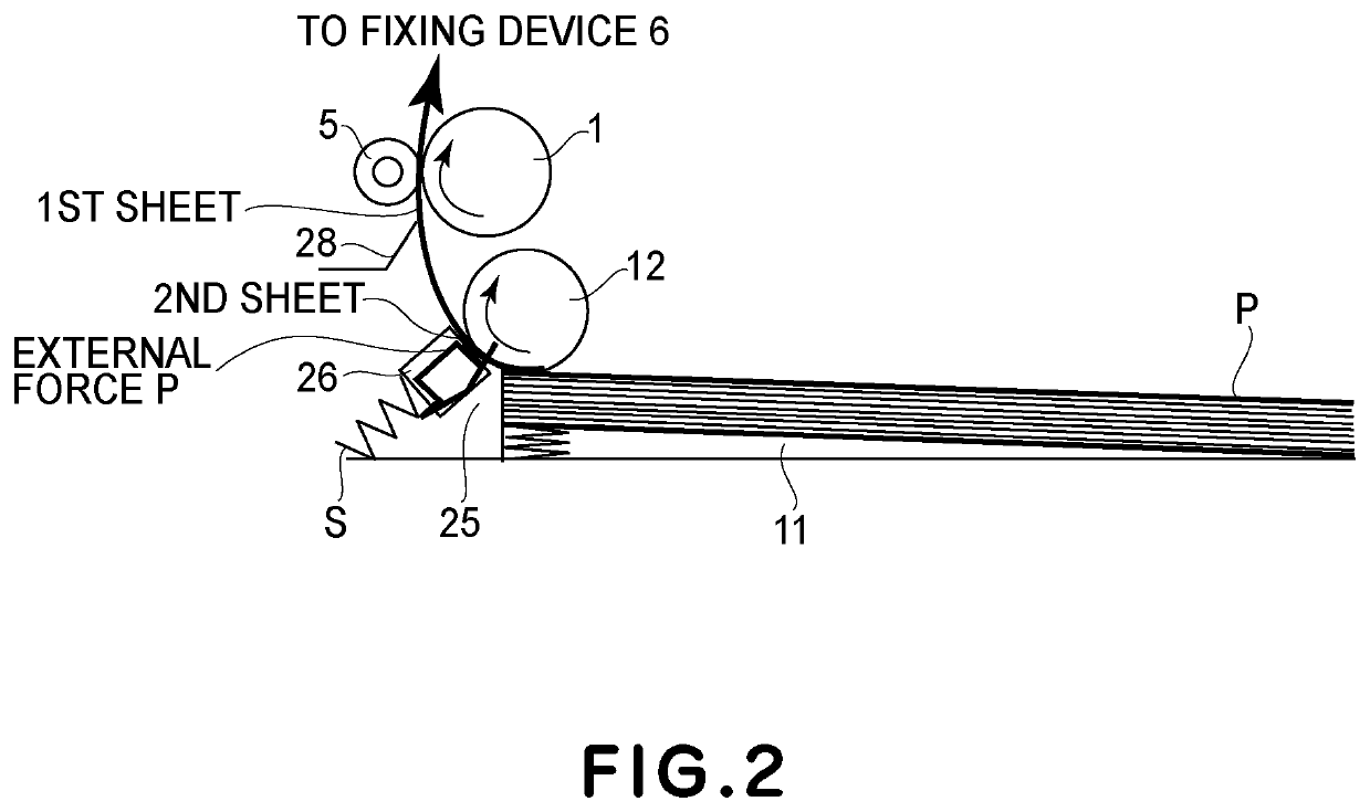
[0161]Another embodiment of the image forming apparatus 50 will be described. The external force exerted on the recording material P in the apparatus main assembly 50a is not limited to the frictional resistance by the separation pad 26 of the sheet feeding portion 25 and the tensile force of the pressing roller 23. In the image forming apparatus 50 in Embodiment 1, after the leading end of the recording material P entered the fixing nip Pd, as the external force, the force was exerted on the recording material P in the direction of pulling the recording material P. For this reason, the apparatus in which the surface movement speed of the photosensitive drum 1 was gradually reduced was described. In this embodiment, an example in which the surface movement speed of the photosensitive drum 1 is increased will be described.

[0162]An image forming apparatus shown in (a) of FIG. 9 has a constitution in which an entrance guide 281 toward the transfer nip Pb entered the photosensitive drum...


PUM


Abstract

An image forming apparatus includes a photosensitive member; an exposure portion configured to expose the photosensitive member to light depending on image information to form a latent image on the photosensitive member; a developing portion configured to develop the latent image into a toner image with toner; and a transfer portion configured to transfer the toner image from the photosensitive member onto a recording material. The image forming apparatus changes a surface movement speed of the photosensitive member at timing prior to predetermined timing, when a moving speed of a recording material at the transfer portion changes, by a predetermined time.

Description

FIELD OF THE INVENTION AND RELATED ART[0001]The present invention relates to an image forming apparatus such as an electrophotographic copying machine or an electrophotographic printer.[0002]An example of the image forming apparatus of an electrophotographic type will be described with reference to FIG. 13. FIG. 13 is a sectional view showing a general structure of the example of the image forming apparatus (monochromatic printer) of the electrophotographic type.[0003]In an image forming apparatus 100, an outer peripheral surface of a photosensitive drum 1 during a rotational operation is electrically charged uniformly to a predetermined potential and a predetermined polarity by a charging roller 2.[0004]At an exposure portion 3 of a laser scanner type, a polygon mirror during a rotational operation is irradiated with laser light L outputted from a laser oscillator. The polygon mirror carries out scanning exposure (laser light irradiation) of the photosensitive drum 1 in a main scan...

Claims


Application Information

Patent Timeline
Patent Type & Authority Applications(United States)
IPC IPC(8): G03G15/00
CPCG03G15/5008G03G15/0415G03G15/6564G03G15/6555G03G15/65G03G15/6529
Inventor SUZUKI, AITANAKA, MASASHIIKEGAMI, SHOICHIROUMEDA, KENSUKETAGUCHI, SHO
Owner CANON KK
Why Eureka
Try Eureka