Platform system

a platform system and platform technology, applied in the direction of building parts, balustrades, constructions, etc., can solve the problems of not being adaptable or reconfigurabl

Active Publication Date: 2020-05-05
SAFERACK
View PDF98 Cites 11 Cited by
  • Summary
  • Abstract
  • Description
  • Claims
  • Application Information

AI Technical Summary

Problems solved by technology

While this provides an acceptable platform for one situation, it is not adaptable or reconfigurable as the situation changes (or for another situation).

Method used


Image

  • Platform system
  • Platform system
  • Platform system

Examples


Embodiment Construction

[0037]It is to be understood by one of ordinary skill in the art that the present discussion is a description of exemplary embodiments only, and is not intended as limiting the broader aspects of the present invention, which broader aspects are embodied in the exemplary constructions.

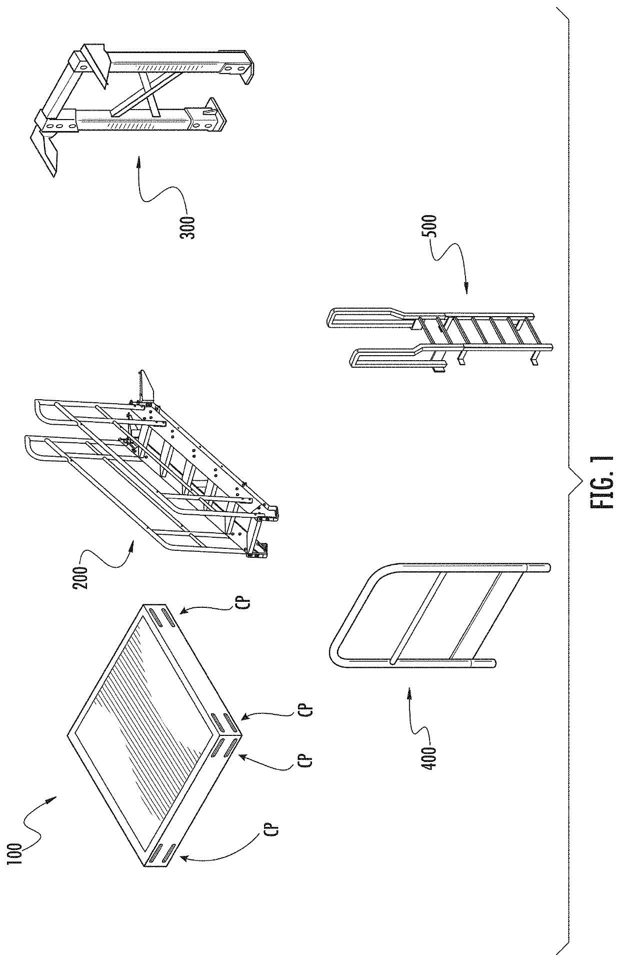
[0038]FIG. 1 illustrates primary components of an exemplary platform system in accordance with an embodiment of the present invention. Such components include modular platform units 100, stair units 200, tower (or “stand”) units 300, platform handrails 400, and ladders 500. The components may be assembled in different ways, and in different combinations, to provide a platform needed in a particular situation. In this case, the illustrated components are compatible and interchangeable with components of the platform system described in the '016 publication. For example, the modular platform units may have a square configuration as shown, with platform connection features CP on side surfaces thereof to wh...


PUM


Abstract

A platform system comprising a platform structure having at least one modular platform unit with platform connection features on a side surface thereof to which other components can be connected, the other components including at least two of the following: another modular platform unit, a stair unit, a tower unit, a handrail unit, and a ladder unit. A stair assembly is connected to the platform structure via said connection features, the stair assembly comprising a plurality of stair units connected together to provide a number of steps equal to the sum of steps of the stair units.

Description

PRIORITY CLAIM[0001]This application is based upon and claims the benefit of U.S. provisional application Ser. No. 62 / 312,260, filed Mar. 23, 2016, which is incorporated fully herein by reference in its entirety for all purposes.FIELD OF THE INVENTION[0002]The present invention relates to modular platform systems, such as are used to provide crossover platforms and access platforms in workplace environments.BACKGROUND OF THE INVENTION[0003]Platform systems are utilized in a variety of industrial and commercial facilities to provide access from one location to another. Generally speaking, such platform systems often fall into one of two categories: crossover platforms and access platforms. Crossover platforms function as bridges, providing a path over some obstruction, such as pipes or industrial machinery. Access platforms, on the other hand, typically allow a user to reach or access a desired area or object from another location.[0004]Usually, platform systems are specially designe...

Claims


Application Information

Patent Timeline
Patent Type & Authority Patents(United States)
IPC IPC(8): E04F11/035E04F11/112E04F11/025E04G27/00E04F11/02E04F11/18
CPCE04F11/112E04F11/035E04F11/025E04G27/00E04F2011/0209E04F2011/1868E04F2011/187
Inventor HONEYCUTT, ROBERT W.LANE, JOSEPH N.JONES, CARSON ALLANKING, JR., PAUL THOMAS
Owner SAFERACK
Why Eureka
Try Eureka