Side action flush lock for casement window and method of operating the same

a casement window and flush lock technology, applied in the field of window locks, can solve the problems of significantly reducing the actuation of the profile lock, not teaching or disclosing a locking mechanism, and not disclosing, describing, or suggesting any type of lifter mechanism, and achieve the effect of minimalism deflection

Active Publication Date: 2020-05-12
INTERLOCK USA
View PDF62 Cites 0 Cited by
  • Summary
  • Abstract
  • Description
  • Claims
  • Application Information

AI Technical Summary

Benefits of technology

[0011]It is a further object of the present invention to provide a casement window lock that allows for complete reversal of the handle from the locking position to the unlocking position, and vice versa.
[0012]In yet another object of the present invention, it is desirable to provide a casement window lock that prevents back driving the locking mechanism.
[0022]A snap-on escutcheon may be attached to the casing and the handle, and the casement window lock may further include a rotatable connector for preventing the handle from over-rotating and contacting the casing and / or escutcheon and ensuring clearance therebetween as the handle is rotated to an unlocked position.

Problems solved by technology

The most relevant prior art does not teach or disclose a locking mechanism capable of low profile (on the order of 8 mm) flush mounting that can be adapted to work with existing tie bar locking designs.
This prior art does not disclose, describe, or suggest any type of lifter mechanism in combination with the fork component to achieve a significantly reduced profile lock actuation.
Nor does this prior art design introduce additional linkage to prevent back driving the lock.

Method used


Image

  • Side action flush lock for casement window and method of operating the same
  • Side action flush lock for casement window and method of operating the same
  • Side action flush lock for casement window and method of operating the same

Examples


Embodiment Construction

)

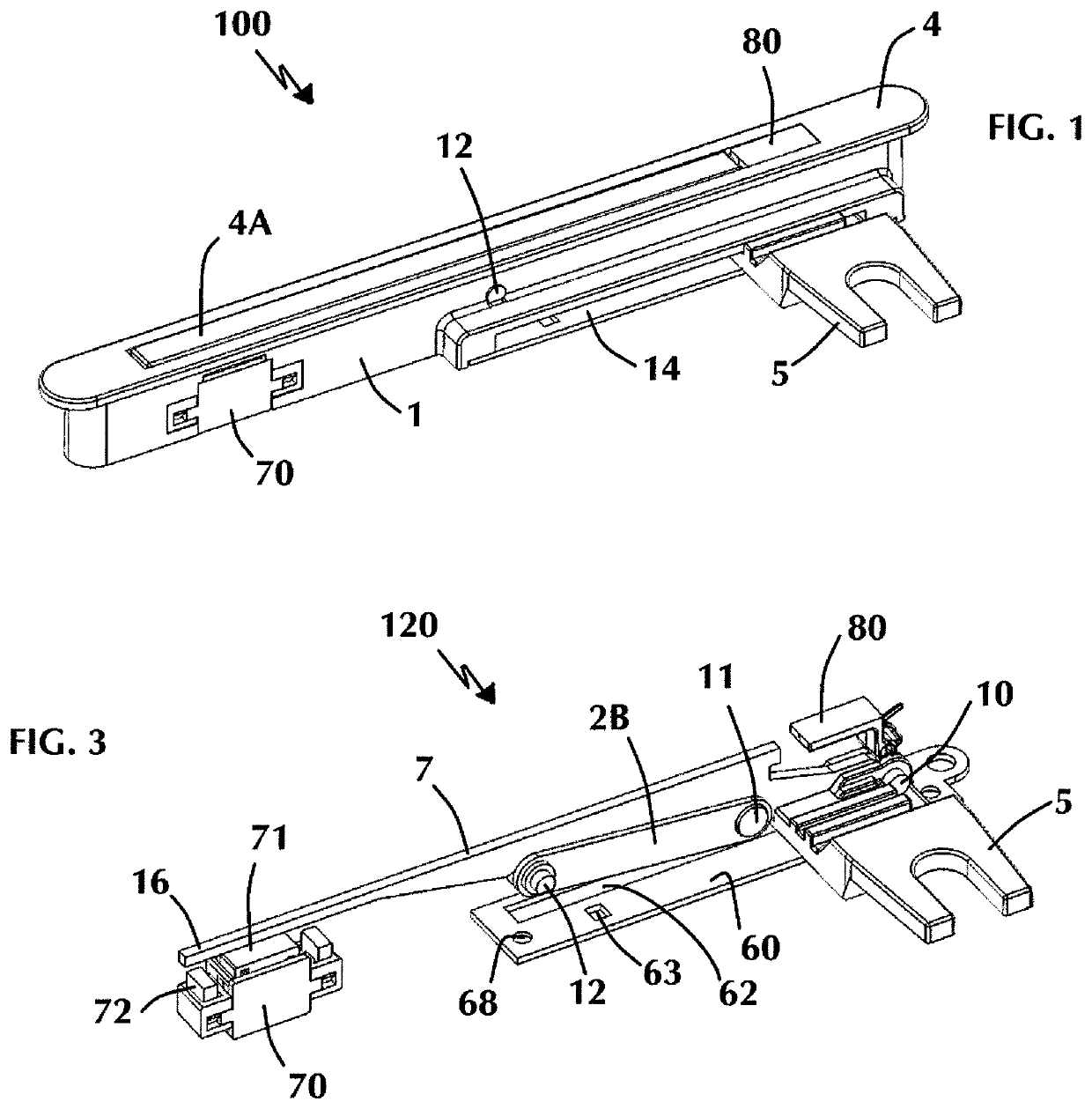
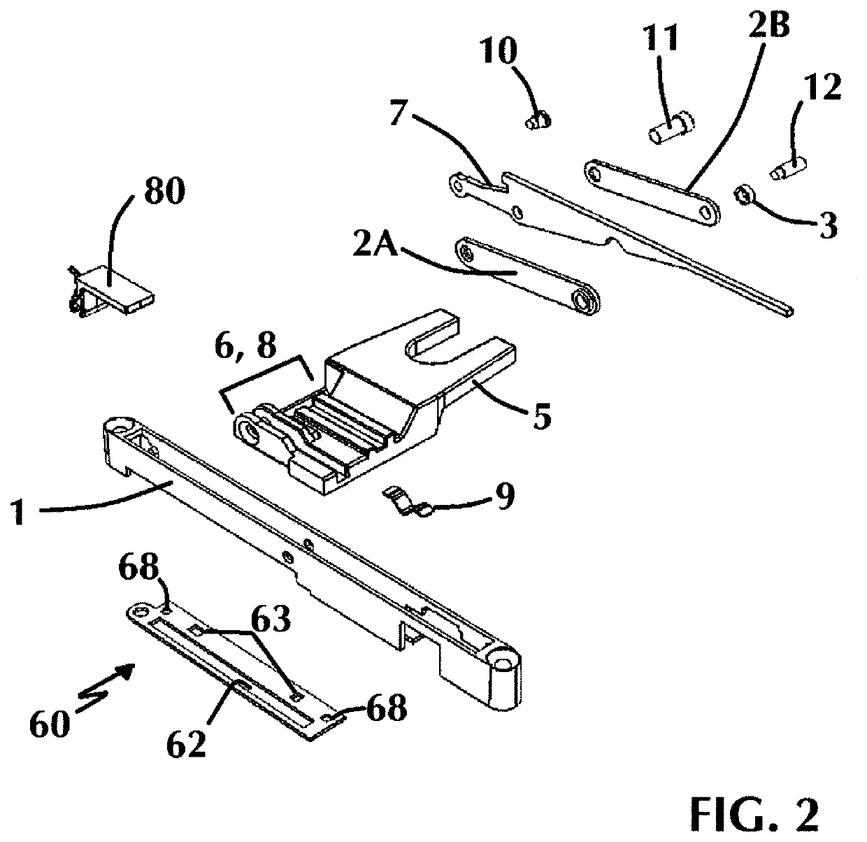
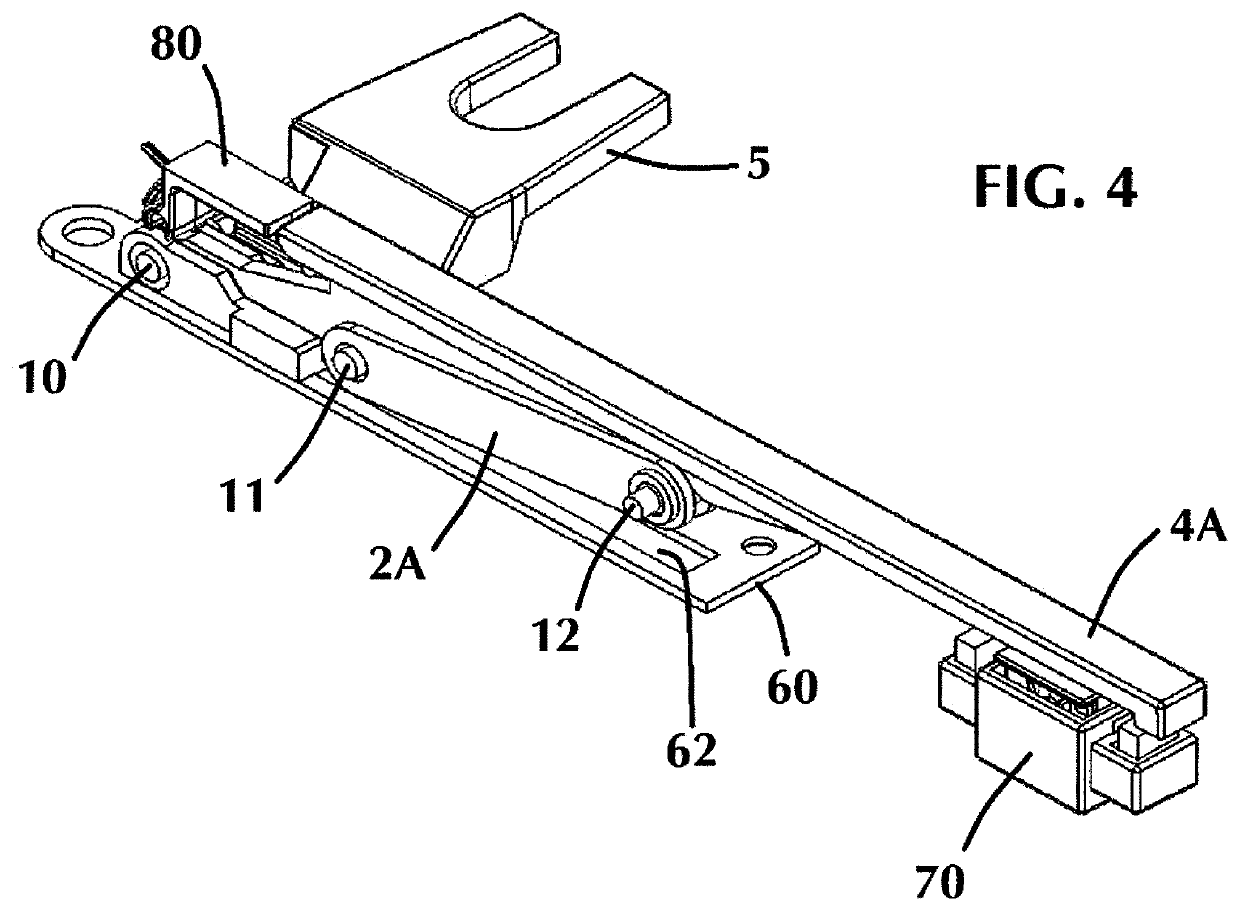
[0039]In describing the embodiments of the present invention, reference will be made herein to FIGS. 1-15 of the drawings in which like numerals refer to like features of the invention.

[0040]Certain terminology is used herein for convenience only and is not to be taken as a limitation of the invention. For example, words such as “upper,”“lower,”“left,”“right,”“horizontal,”“vertical,”“upward,” and “downward” merely describe the configuration shown in the drawings. For purposes of clarity, the same reference numbers will be used in the drawings to identify similar elements.

[0041]The lock of the present invention is a low profile, flush design, that protrudes from the window frame significantly less than the prior art, at about 8 mm compared to 25 mm in the current prior art designs. When locking a casement window, the window is closed generally by a crank. The strikes on the moving sash are brought close to the pins on a tie bar mounted to the non-moving window frame. The lock handle...


PUM


Abstract

A low profile actuating window lock for casement windows having a longitudinal slot in a sidewall of the casing for the lock, wherein a fork component translates within the slot in a direction perpendicular to an axis of rotation of the handle and the handle rotates along a plane perpendicular to the fork component, the handle pivotable about a restrictor arm that pivots relative to the casing, allowing the handle to rotate fully from the locked position to the unlocked position with low clearance from the window frame. The pivot points of the handle and restrictor arm configuration allow for an over center linkage that prevents back driving the casement window lock.

Description

RELATED APPLICATIONS[0001]This application is a continuation-in-part of U.S. patent application Ser. No. 14 / 793,820 filed Jul. 8, 2015, which is a divisional application of U.S. patent application Ser. No. 13 / 610,789 filed Sep. 11, 2012.BACKGROUND OF THE INVENTION1. Field of the Invention[0002]The present invention is directed towards window locks, and more particularly toward manual handles for actuating window locks. Specifically, the present invention is directed to a flush mounted or low profile actuating window lock for casement windows. More specifically, the present invention is directed to a flush mounted lock actuator designed to drive a lock bar that locks and unlocks a casement window, which protrudes from the window frame significantly less than prior art designs, while employing an action which operates at 90 degrees to the pivoting handle.2. Description of Related Art[0003]Generally, a casement window is a window unit in which the single vent cranks outward, to the rig...

Claims


Application Information

Patent Timeline
Patent Type & Authority Patents(United States)
IPC IPC(8): E05B5/00E05B15/00E05B9/08E05C9/10E05C9/02E05C1/08E05C17/48E05C17/14E05C19/02E05C1/00E05C9/22E05C19/10E05C9/20E05C1/02
CPCE05B9/08E05B5/006E05B15/0006E05C9/10E05C2001/008E05C19/028E05C1/004E05C9/02E05C9/20Y10T292/0963E05C1/08E05C17/14Y10T292/0967E05C19/10E05C17/48Y10T292/0951Y10T292/0968E05C9/22E05C1/006E05C1/02E05B5/00E05B15/0073E05B15/0086E05C1/00
Inventor MINTER, PETER J.RUSPIL, MATHEW D.
Owner INTERLOCK USA
Why Eureka
Try Eureka