Straight action flush lock for casement window and method of operating the same

a casement window and lock technology, applied in the field of window locks, can solve the problems of significantly reducing the actuation of the profile lock, not teaching or disclosing a locking mechanism, and not disclosing, describing, or suggesting any type of linkage, so as to prevent the back driving of the locking mechanism

Active Publication Date: 2021-09-14
INTERLOCK USA
View PDF64 Cites 1 Cited by
  • Summary
  • Abstract
  • Description
  • Claims
  • Application Information

AI Technical Summary

Benefits of technology

[0010]It is a further object of the present invention to provide a casement window lock that allows for reversal of the handle from the locking position to the unlocking position, and vice versa.
[0011]In yet another object of the present invention, it is desirable to provide a casement window lock that prevents back driving the locking mechanism.
[0018]In an embodiment, the lock may further include a rotatable position stop for preventing the handle from over-rotating and contacting the casing and ensuring clearance therebetween as the handle is rotated to an unlocked position.

Problems solved by technology

The most relevant prior art does not teach or disclose a locking mechanism capable of low profile (on the order of 8 mm) flush mounting that can be adapted to work with existing tie bar locking designs.
This prior art does not disclose, describe, or suggest any type of linkage in combination with the fork component to achieve a significantly reduced profile lock actuation.
Nor does this prior art design introduce additional linkage to prevent back driving the lock.

Method used


Image

  • Straight action flush lock for casement window and method of operating the same
  • Straight action flush lock for casement window and method of operating the same
  • Straight action flush lock for casement window and method of operating the same

Examples


Embodiment Construction

)

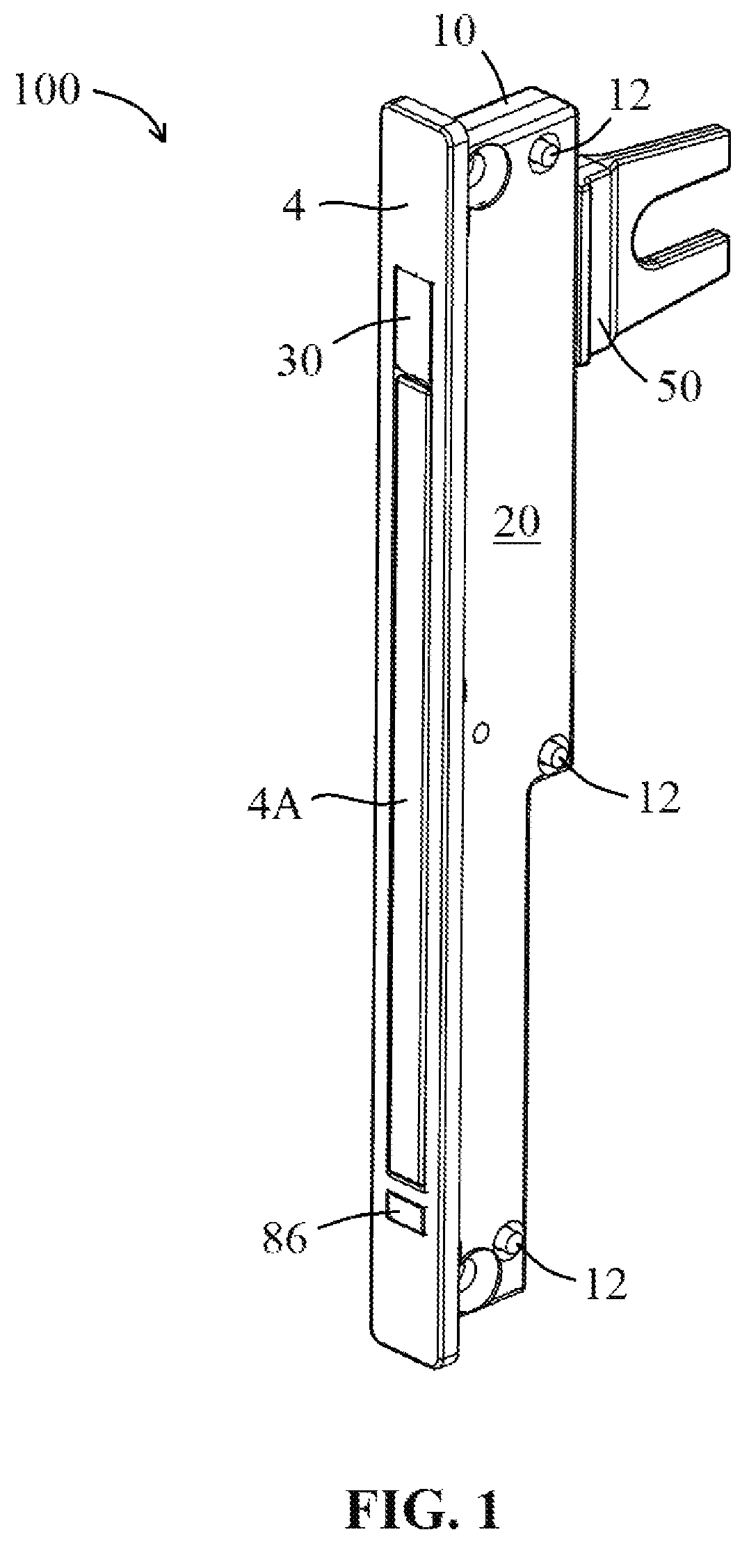
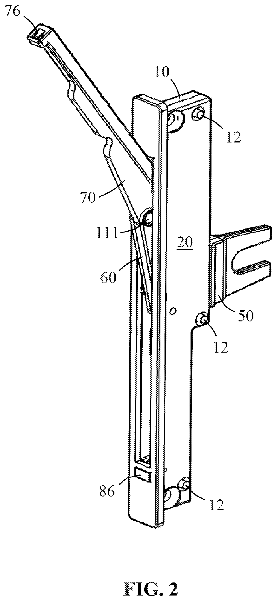
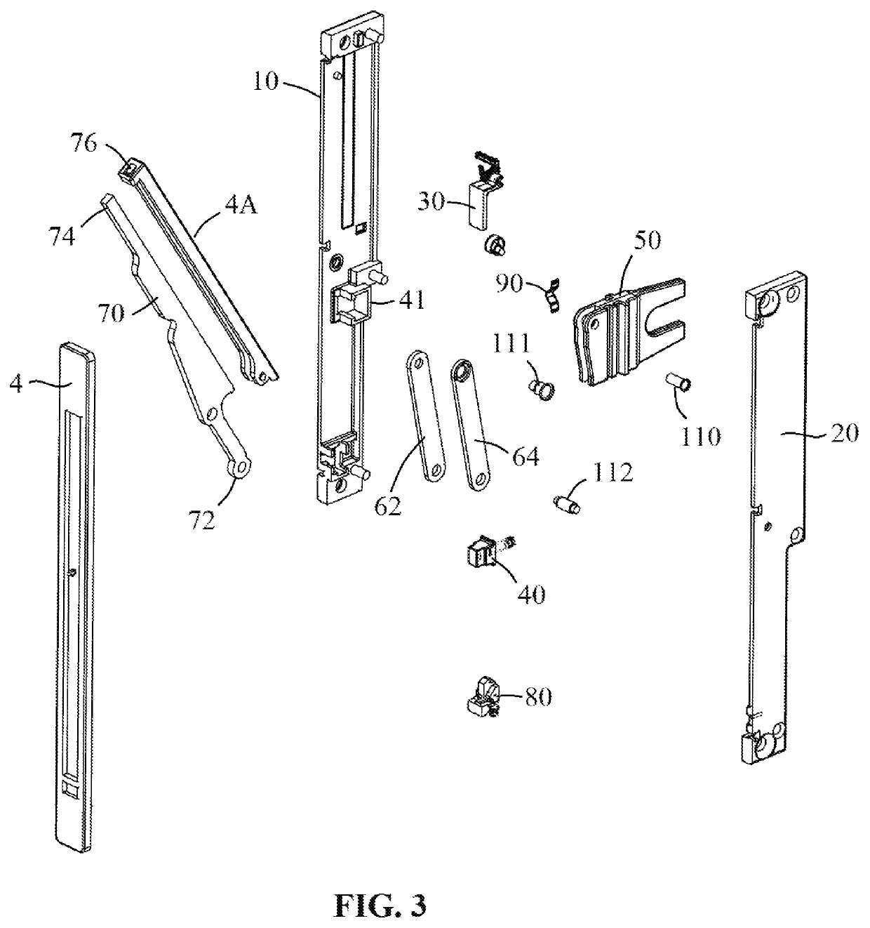
[0037]In describing the embodiments of the present invention, reference will be made herein to FIGS. 1-17 of the drawings in which like numerals refer to like features of the invention.

[0038]Certain terminology is used herein for convenience only and is not to be taken as a limitation of the invention. For example, words such as “upper,”“lower,”“left,”“right,”“front,”“rear,”“horizontal,”“vertical,”“upward,”“downward,”“clockwise,”“counterclockwise,”“longitudinal,”“lateral,” or the like, merely describe the configuration shown in the drawings. Indeed, the referenced components may be oriented in any direction and the terminology, therefore, should be understood as encompassing such variations unless specified otherwise. For purposes of clarity, the same reference numbers may be used in the drawings to identify similar elements.

[0039]Additionally, in the subject description, the words “exemplary,”“illustrative,” or the like, are used to mean serving as an example, instance or illustra...


PUM


Abstract

A low profile actuating window lock for casement windows having a longitudinal slot in a sidewall of the casing for the lock, wherein an actuator including a fork component translates within the slot in a direction opposite movement of the handle, the handle pivotable about a restrictor arm that pivots relative to the casing, allowing the handle to rotate from the locked position to the unlocked position with low clearance from the window frame. The pivot points of the handle and restrictor arm configuration allow for an over center linkage that prevents back driving the casement window lock.

Description

BACKGROUND OF THE INVENTION1. Field of the Invention[0001]The present invention is directed towards window locks, and more particularly toward manual handles for actuating window locks. Specifically, the present invention is directed to a flush mounted or low profile actuating window lock for casement windows. More specifically, the present invention is directed to a flush mounted lock actuator designed to drive a lock bar that locks and unlocks a casement window, which protrudes from the window frame significantly less than prior art designs, while employing linkage to prevent the actuator from being back driven from either the locked position or unlocked position.2. Description of Related Art[0002]Generally, a casement window is a window unit in which the single vent cranks outward, to the right or left. Casement windows are hinged at the side. (Windows hinged at the top are referred to as awning windows.) They are used singly or in pairs within a common frame. Casement windows ar...

Claims


Application Information

Patent Timeline
Patent Type & Authority Patents(United States)
IPC IPC(8): E05B5/00E05C19/10E05B15/00E05C9/10E05C9/20E05C17/14E05C1/08E05C9/02E05C1/00E05C9/22E05C1/02E05C19/02E05B85/22E05C17/48
CPCE05B5/006E05B5/00E05B15/0006E05C9/10E05C19/10E05B85/22E05C1/00E05C1/002E05C1/006E05C1/02E05C1/08E05C9/02E05C9/028E05C9/20E05C9/22E05C17/14E05C17/48E05C19/028E05C2001/008Y10S292/31Y10S292/47Y10S292/62Y10T292/0951Y10T292/0963Y10T292/0967Y10T292/0968E05C19/022
Inventor MINTER, PETER J.
Owner INTERLOCK USA
Why Eureka
Try Eureka