Imaging lens
a technology of imaging and lens, applied in the field of imaging lenses, can solve the problems of a ratio of the total track length to the focal length of the overall optical system being too large, and achieve the effects of small telephoto ratio, low f-number, and high resolution performan
- Summary
- Abstract
- Description
- Claims
- Application Information
AI Technical Summary
Benefits of technology
Problems solved by technology
Method used
Image

Examples
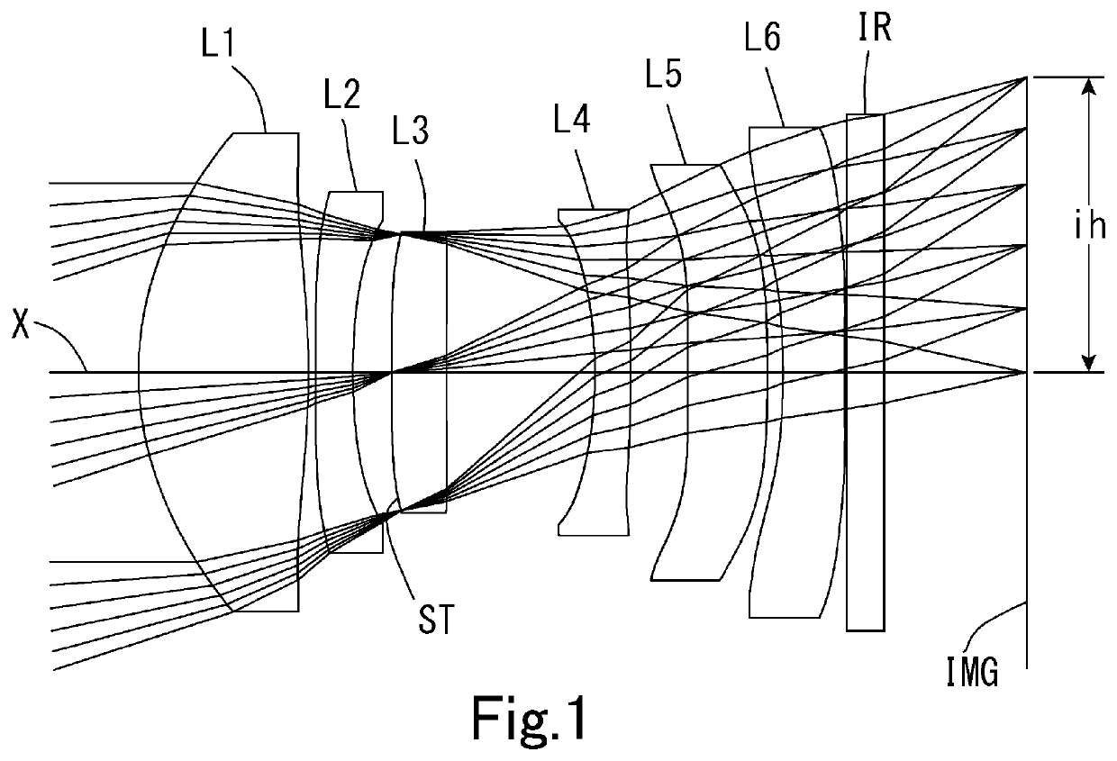
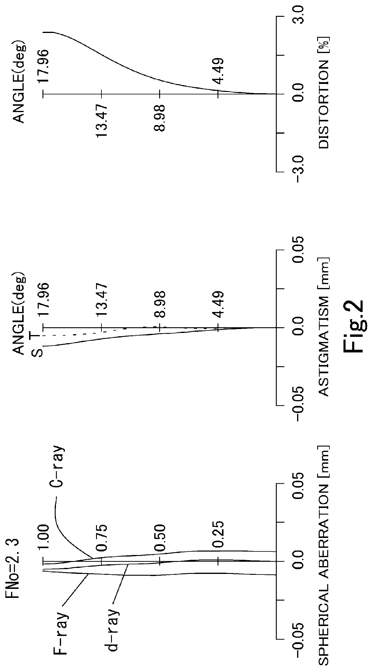
example 1
[0133]The basic lens data is shown below in Table 1.
[0134]
TABLE 1Example1Unit mmf = 4.95ih = 1.66Fno = 2.3TTL = 4.87ω(°) = 18.0Surface DataSurfaceCurvatureSurfaceRefractiveAbbeNumber iRadius rDistance dIndex NdNumber νd(Object)InfinityInfinity 1*1.78020.94611.54455.86 (νd1) 2*−4.43780.0400 3*132.26690.20701.66120.37 (νd2) 4*3.60000.2170 5* (Stop)Infinity0.30371.53555.66 6*Infinity0.8258 7*−3.04910.20001.54455.86 (νd4) 8*−25.42160.3156 9*18.67880.44521.66120.37 (νd5)10*−10.71560.086111*−5.40590.34441.53555.6612*10.41620.010113Infinity0.21001.51764.1714Infinity0.7883Image PlaneInfinityConstituent Lens DataLensStart SurfaceFocal Length112.47bf = 0.9423−5.6035Infinityph = 0.3547−6.395910.37EPsd = 1.06611−6.60Aspheric Surface DataFirst SurfaceSecond SurfaceThird SurfaceFourth SurfaceFifth SurfaceSixth Surfacek−1.660269E+00 −1.191489E+01 0.000000E+00−3.259898E+00 0.000000E+000.000000E+00A42.469511E−024.071218E−024.833220E−027.758519E−021.213871E−017.591957E−03A6−2.048790E−03 2.749852E...
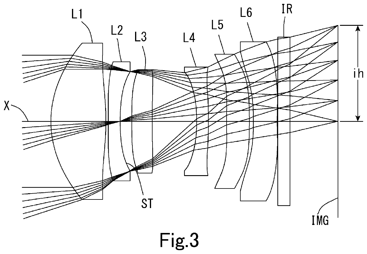
example 2
[0137]The basic lens data is shown below in Table 2.
[0138]
TABLE 2Example2Unit mmf = 4.95ih = 1.66Fno = 2.3TTL = 4.87ω(°) = 18.0Surface DataSurfaceCurvatureSurfaceRefractiveAbbeNumber iRadius rDistance dIndex NdNumber νd(Object)InfinityInfinity 1*1.76640.94591.54455.86 (νd1) 2*−4.62980.0400 3*132.26690.20701.66120.37 (νd2) 4* (Stop)3.60000.2000 5*19.40160.35301.53555.66 6*23.19660.7661 7*−3.01880.20001.54455.86 (νd4) 8*−36.07510.3146 9*14.72260.39291.66120.37 (νd5)10*−10.58410.070011*−5.16370.40921.53555.6612*10.34670.010113Infinity0.21001.51764.1714Infinity0.8201Image PlaneInfinityConstituent Lens DataLensStart SurfaceFocal Length112.48bf = 0.9723−5.6035214.78ph = 0.3647−6.07599.38EPsd = 1.06611−6.38Aspheric Surface DataFirst SurfaceSecond SurfaceThird SurfaceFourth SurfaceFifth SurfaceSixth Surfacek−1.673981E+00 −1.039706E+01 0.000000E+00−2.255780E+00 0.000000E+000.000000E+00A42.561807E−022.100059E−022.009929E−026.863143E−021.223477E−011.630633E−03A6−1.798525E−03 1.189120E−012....
example 3
[0141]The basic lens data is shown below in Table 3.
[0142]
TABLE 3Example3Unit mmf = 4.95ih = 1.66Fno = 2.3TTL = 4.87ω(°) = 18.0Surface DataSurfaceCurvatureSurfaceRefractiveAbbeNumber iRadius rDistance dIndex NdNumber νd(Object)InfinityInfinity 1*1.74820.89421.54455.86 (νd1) 2*−4.57260.0400 3* (Stop)132.26690.20701.66120.37 (νd2) 4*3.60000.2000 5*18.13830.36421.53555.66 6*18.05020.7476 7*−2.99800.21301.54455.86 (νd4) 8*−39.19730.3124 9*13.88170.35391.66120.37 (νd5)10*−10.50540.070011*−5.13200.50211.53555.6612*10.48300.010113Infinity0.21001.51764.1714Infinity0.8137Image PlaneInfinityConstituent Lens DataLensStart SurfaceFocal Length112.45bf = 0.9623−5.603515772.98ph = 0.3847−5.98599.10EPsd = 1.06611−6.37Aspheric Surface DataFirst SurfaceSecond SurfaceThird SurfaceFourth SurfaceFifth SurfaceSixth Surfacek−1.658170E−00 −1.046659E+01 0.000000E+00−2.358967E+00 0.000000E+000.000000E−00A42.621230E−021.270284E−021.195607E−026.743211E−021.214149E−01−8.820284E−04 A6−1.860909E−03 1.488725E...
PUM
 Abstract
Description
Claims
Application Information
 - R&D
- Intellectual Property
- Life Sciences
- Materials
- Tech Scout
- Unparalleled Data Quality
- Higher Quality Content
- 60% Fewer Hallucinations
Browse by: Latest US Patents, China's latest patents, Technical Efficacy Thesaurus, Application Domain, Technology Topic, Popular Technical Reports.
© 2025 PatSnap. All rights reserved.Legal|Privacy policy|Modern Slavery Act Transparency Statement|Sitemap|About US| Contact US: help@patsnap.com