Imaging lens
a technology of imaging and lens, applied in the field of imaging lenses, to achieve the effect of small telephoto ratio, low f-number in well-balanced, and high resolution
- Summary
- Abstract
- Description
- Claims
- Application Information
AI Technical Summary
Benefits of technology
Problems solved by technology
Method used
Image

Examples
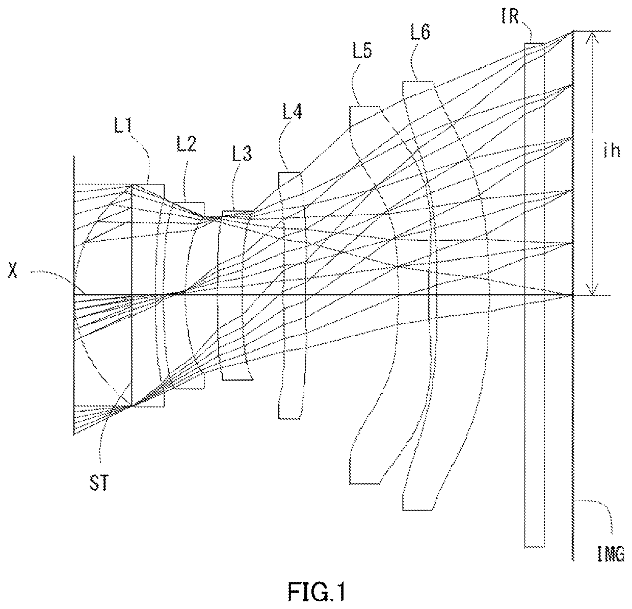
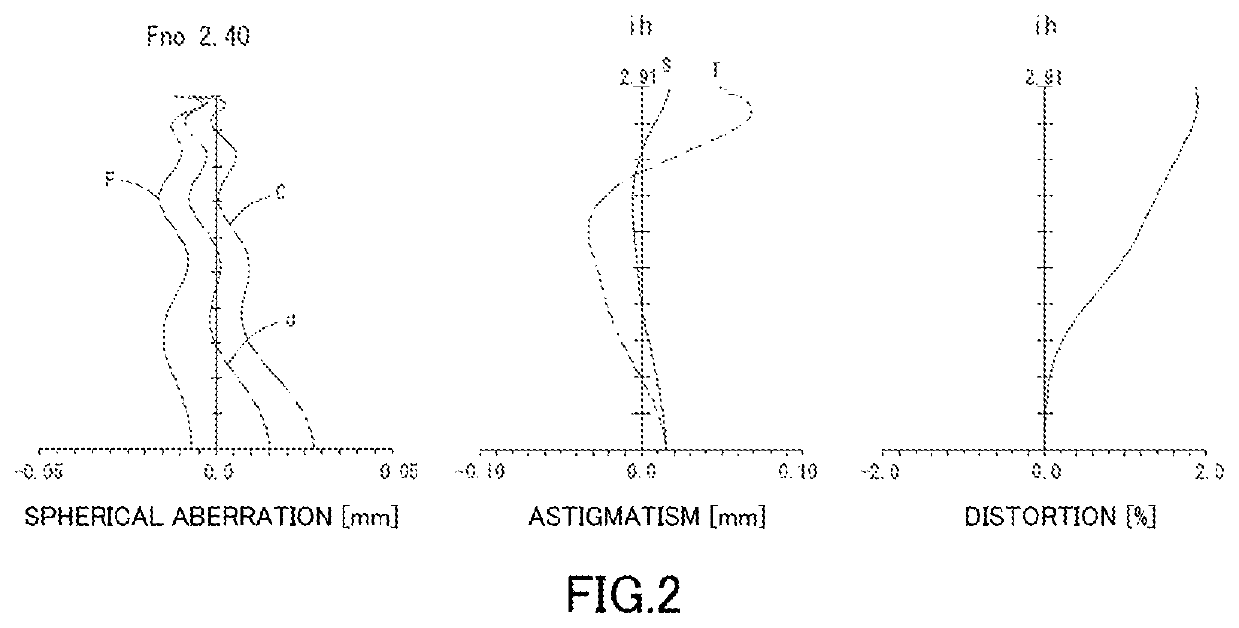
example 1
[0246]The basic lens data is shown below in Table 1.
[0247]
TABLE 1Example 1Unit mmf = 5.89Fno = 2.40ω(*) = 26.0i h = 2.91TTL = 5.44Surface DataSurfaceCurvatureSurfaceRefractiveAbbeNumber iRadius rDistance dIndex NdNumber νd(Object)InfinityInfinity1(Stop)Infinity−0.6408 2*1.48270.89501.54455.86 (νd1) 3*7.34070.0899 4*4.71680.24001.67119.48 (νd2) 5*2.20000.3559 6*6.51300.27001.53555.66 (νd3) 1*4.41560.4576 8*5.61890.24301.67119.48 (νd4) 9*6.97201.023910*−16.0922 0.33501.54455.86 (νd5)11*4.22250.090012*Infinity0.57971.67119.48 (νd6)13*−13.8009 0.400014 Infinity0.21001.51764.2015 Infinity0.3068Image PlaneInfinityConstituent Lens DataStartFocalEntrance pupilLensSurfaceLengthdiameter123.239EPD 2.45024−6.39136−26.8434840.261510−6.11061220.574Aspheric Surface DataSecondThirdFourthFifthSixthSeventhSurfaceSurfaceSurfaceSurfaceSurfaceSurfacek0.000000E+000.000000E+00 0.000000E+000.000000E+000.000000E+000.000000E+00A4−7.638400E−04 −1.032419E−01 −2.778076E−01−2.559684E−01 −1.924440E−01 −1.893077E−...
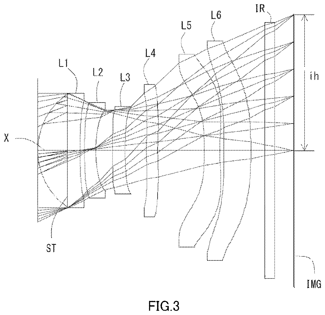
example 2
[0250]The basic lens data is shown below in Table 2.
[0251]
TABLE 2Example 2Unit mmf = 5.89Fno = 2.40ω(*) = 26.0i h = 2.91TTL = 5.44Surface DataSurfaceCurvatureSurfaceRefractiveAbbeNumber iRadius rDistance dIndex NdNumber νd(Object)InfinityInfinity1(Stop)Infinity−0.6441 2*1.48260.90601.54455.86 (νd1) 3*8.25020.0975 4*5.05110.24001.67119.48 (νd2) 5*2.20290.3625 6*7.58130.27001.53555.66 (νd3) 7*4.71830.4571 8*4.66470.24391.67119.48 (νd4) 9*5.58190.998910*−14.4325 0.33501.54455.86 (νd5)11*4.47640.090012*Infinity0.57921.67119.48 (νd6)13*−13.4677 0.300014 Infinity0.21001.51764.2015 Infinity0.4062Image PlaneInfinityConstituent Lens DataStartFocalEntrance pupilLensSurfaceLengthdiameter123.171EPD 2.45024−6.02836−24.1574838.237510−6.23861220.077Aspheric Surface DataSecondThirdFourthFifthSixthSeventhSurfaceSurfaceSurfaceSurfaceSurfaceSurfacek0.000000E+000.000000E+00 0.000000E+000.000000E+000.000000E+000.000000E+00A41.110720E−03−1.001271E−01 −3.039921E−01−2.949919E−01 −2.304971E−01 −2.258548E−01...
example 3
[0254]The basic lens data is shown below in Table 3.
[0255]
TABLE 3Example 3Unit mmf = 5. 84Fno = 2.41ω(*) = 26.3i h = 2.91TTL = 5.42Surface DataSurfaceCurvatureSurfaceRefractiveAbbeNumber iRadius rDistance dIndex NdNumber νd(Object)InfinityInfinity1(Stop)Infinity−0.5907 2*1.53460.85591.54455.86 (νd1) 3*8.73850.1171 4*6.16700.24001.66120.37 (νd2) 5*2.40170.2659 6*3.93940.27001.53555.86 (νd3) 7*4.58490.5854 8*Infinity0.24001.66120.37 (νd4) 9*Infinity0.756410*87.9816 0.33711.54455.86 (νd5)11*4.01690.234412*−13.8533 0.66781.66120.37 (νd6)13*−22.0494 0.400014 Infinity0.21001.51764.2015 Infinity0.3103Image PlaneInfinityConstituent Lens DataStartFocalEntrance pupilLensSurfaceLengthdiameter123.283EPD 2.42024−6.1083645.66248Infinity510−7.744612−58.293Aspheric Surface DataSecondIhirdFourthFifthSixthSeventhSurfaceSurfaceSurfaceSurfaceSurfaceSurfacek0.000000E+000.000000E+00 0.000000E+00 0.000000E+000.000000E+000.000000E+00A4−2.360111E−03 −1.029233E−01 −2.987961E−01−3.107843E−01−2.008954E−01 −1.0...
PUM
 Abstract
Description
Claims
Application Information