Imaging lens
a technology of imaging and lens, applied in the field of imaging lenses, can solve the problems of inability to obtain excellent optical performance, difficult to correct aberrations at a peripheral area, etc., and achieve the effects of low f-number, correcting aberrations properly, and high resolution
- Summary
- Abstract
- Description
- Claims
- Application Information
AI Technical Summary
Benefits of technology
Problems solved by technology
Method used
Image

Examples
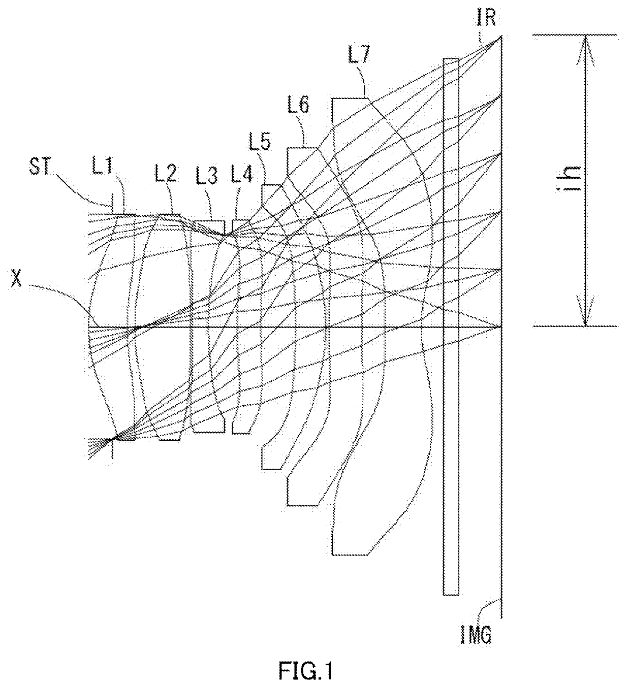
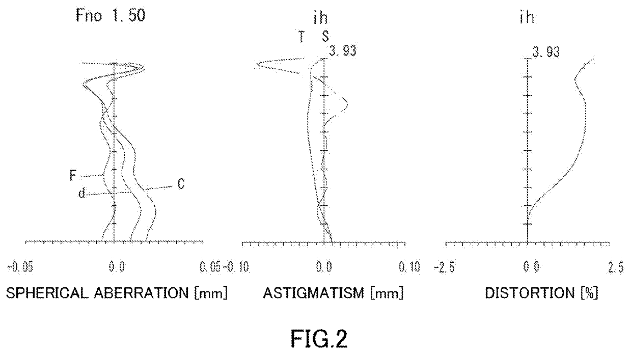
example 1
[0109]The basic lens data is shown below in Table 1.
TABLE 1Example 1Unit mmf = 4.69 = 3.93 = 1.50TTL = 5.58ω(*) = 39.4Surface DataSurfaceCurvatureSurfaceNumber iRadius rDistance dRefractiveAbbe(Object)InfinityInfinityIndex NdNumber vd1(Stop)Infinity-0.32042*2.07360.52001.54455.88(v d1)3*2.92090.10374*2.80040.75831.54455.86(v d2)5*-68.81890.03006*-44.98760.22001.86120.37(v d3)7*5.36470.39108*5.15860.31871.68120.37(v d4)9*6.88700.472510*-8.28570.41161.53585.66(v d5)11*-2.51300.045112*Infinity0.45001.68120.37(v d6)13*Infinity0.302314*17.35470.50211.53565.66(v d7)15*1.85860.300018Infinity0.21001.51704.2019Infinity0.5740Image PlansInfinityConstituent Lens DataStart Focal LensSurfaceLengthComposite Focal Length1210.798167-3.936244.95236-7.2414828.9075106.501612Infinity714-3.935Aspheric Surface DataSecond Third Fourth Fifth SurfaceSurfaceSurfaceSurfacek-9.439083E-01-1.909210E+01-1.381746E+010.000000E+00A4-1.379402E-022.780187E-022.815085E-02-7.557235E-02A64.083157E-02-1.242574E-01-7.580091...
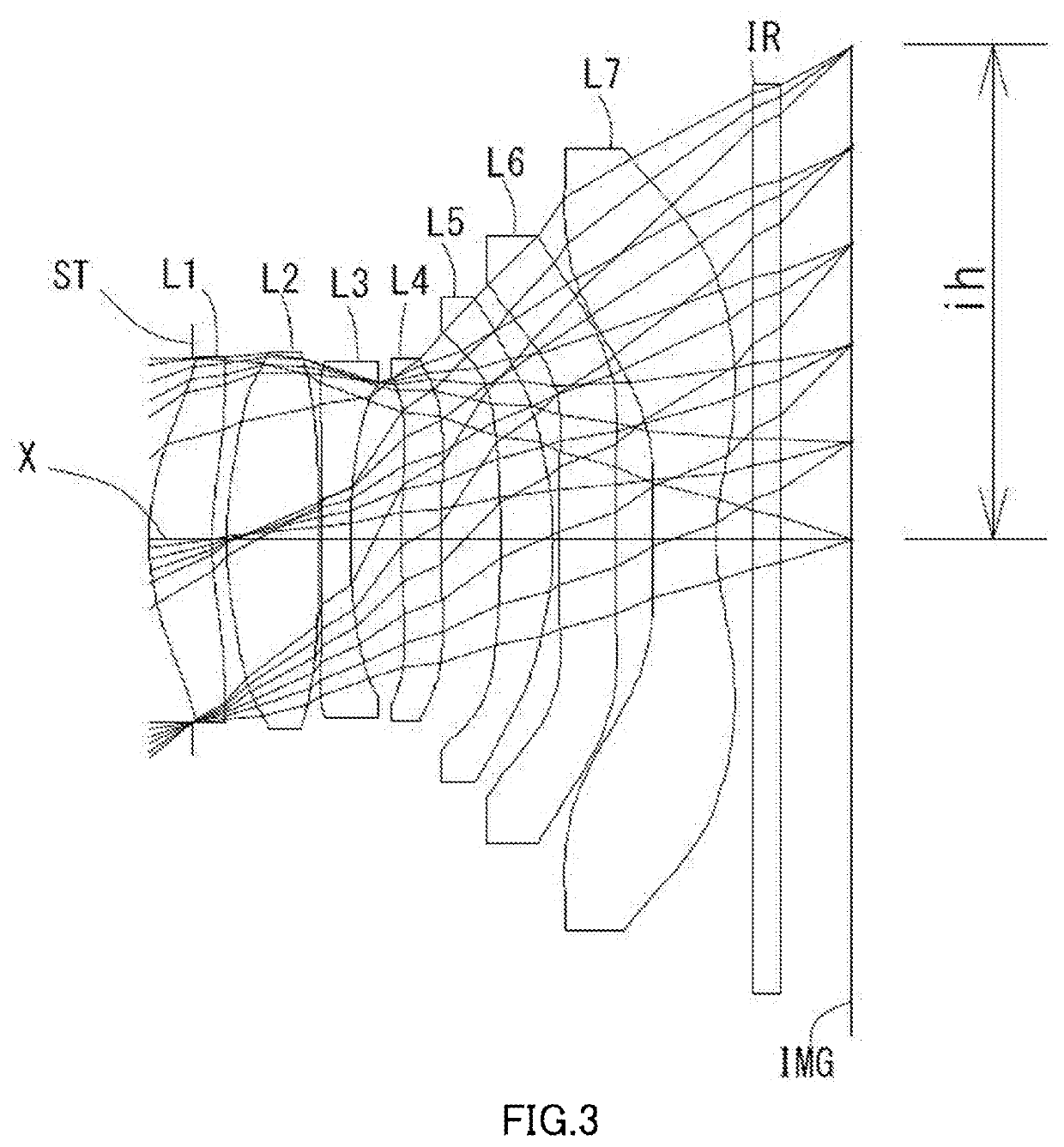
example 2
[0112]The basic lens data is shown below in Table 2.
TABLE 2Example 2Unit mmf = 4.70 = 3.93 = 1.60TTL = 5.53ω(*) = 39.4Surface DataSurfaceCurvatureSurfaceNumber iRadius rDistance dRefractiveAbbe(Object)InfinityInfinityIndex NdNumber vd1(Stop)Infinity-0.32042*2.08740.50451.54655.88(v d1)3*2.03740.11304*2.80710.73731.54455.86(v d2)5*-52.68400.03006*-50.90000.22001.86120.37(v d3)7*8.06270.40478*5.28320.31781.86120.37(v d4)9*7.12130.479810*-8.29520.42071.53565.86(v d5)11*-2.48920.041812*Infinity0.45001.66120.27(v d6)13*Infinity0.302314*10.16250.80191.53555.66(v d7)15*1.83830.300018Infinity0.21001.51764.2019Infinity0.5700Image PlansInfinityConstituent Lens DataStart Focal LensSurfaceLengthComposite Focal Length1210.843167-3.842244.91936-7.0854828.0855105.485612Infinity714-3.842Aspheric Surface DataSecond Third Fourth Fifth SurfaceSurfaceSurfaceSurfacek-8.680707E-01-1.000178E+01-1.365274E+010.000000E+00A4-7.200435E-032.589394E-023.034051E-02-5.000264E-02A61.162181E-02-1.254835E-01-9.905854...
example 3
[0115]The basic lens data is shown below in Table 3.
TABLE 3Example 3Unit mmf = 4.75 = 3.83 = 1.60TTL = 5.53ω(*) = 39.1Surface DataSurfaceCurvatureSurfaceNumber iRadius rDistance dRefractiveAbbe(Object)InfinityInfinityIndex NdNumber vd1(Stop)Infinity-0.37282*2.08950.51331.54455.86(v d1)3*3.35820.14344*3.07800.65141.54455.86(v d2)5*-71.53470.03246*241.87580.22001.68120.37(v d3)7*4.50000.42608*5.60590.81181.68120.37(v d4)9*7.56500.492310*-8.66130.42321.53556.66(v d5)11*-2.62570.031612*Infinity0.45001.66120.37(v d6)13*Infinity0.323214*15.31040.50001.53555.66(v d7)15*1.81200.300018Infinity0.21001.51704.2019Infinity0.5700Image PlansInfinityConstituent Lens DataStart Focal LensSurfaceLengthComposite Focal Length128.800187-3.885245.43536-6.9424830.9105106.801612Infinity714-3.895Aspheric Surface DataSecond Third Fourth Fifth SurfaceSurfaceSurfaceSurfacek-9.434785E-01-1.933237E-01-1.262389E+010.000000E+00A4-1.001367E-026.440275E-031.478432E-02-4.969667E-02A63.034898E-02-8.213868E-02-3.683202E...
PUM
 Abstract
Description
Claims
Application Information
 - R&D
- Intellectual Property
- Life Sciences
- Materials
- Tech Scout
- Unparalleled Data Quality
- Higher Quality Content
- 60% Fewer Hallucinations
Browse by: Latest US Patents, China's latest patents, Technical Efficacy Thesaurus, Application Domain, Technology Topic, Popular Technical Reports.
© 2025 PatSnap. All rights reserved.Legal|Privacy policy|Modern Slavery Act Transparency Statement|Sitemap|About US| Contact US: help@patsnap.com