Multifunctional textile sensor

a textile sensor and multi-functional technology, applied in weaving, pulse technique, instruments, etc., can solve the problems of malfunction of capacitive sensors, achieve the effects of reducing thickness, avoiding perforation, and increasing mechanical robustness of the structur

Active Publication Date: 2020-06-30
CONTINENTAL IND TEXTIL DO AVE SA
View PDF14 Cites 1 Cited by
  • Summary
  • Abstract
  • Description
  • Claims
  • Application Information

AI Technical Summary

Benefits of technology

[0010]The use of a specific knitting textile structure typically called Jersey structure or double structures such as interlock, spacer and double faced, for the textile sensor production, allow the use of different mixtures of different yarns materials, which results in a functional and flexible self-capacitive sensor with the mechanical properties of a typical textile structure and the same touch comfort.
[0138]The present application uses electrical conductive yarns knitted simultaneously with different materials that are part of the textile structure, for the sensor production. The materials used in the present application as conductive wires are copper and / or stainless steel and / or silver and / or tungsten and / or molybdenum with diameters between 25 and 150 μm. The use of inorganic conductive materials on the construction of the present textile capacitive sensor and the possibility of knitting the textile sensor and textile structure together, guarantees the possibility of maintain the comfort, seamless and mechanical flexibility of the textile structure.

Problems solved by technology

Several problems had to be overcome during the development of the disclosed textile, namely, the large open areas present in the textile web, which caused difficulties during the printing steps, and electric interferences caused by the electroluminescent device when the junction of the two technologies is necessary, that caused malfunctions of the capacitive sensor.

Method used


Image

  • Multifunctional textile sensor
  • Multifunctional textile sensor
  • Multifunctional textile sensor

Examples


Embodiment Construction

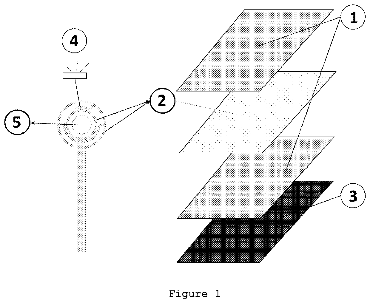
[0166]The present application describes a multifunctional textile that comprises the integration of lighting and sensing capabilities using innovative methods and technologies. The introduction of lighting capabilities is made possible by using two possible types of devices, namely, electroluminescent devices or LEDs. Through the use of different technologies, temperature, humidity, touch and proximity sensing capabilities are also introduced into a textile substrate.

[0167]In relation to their structure and composition, the electroluminescent device and touch sensor comprising thin layers of conductive, electroluminescent and dielectric materials, applied using at least one printing and / or coating technique. As for the LEDs and temperature and humidity sensors, these are bulk electronic devices. A self-capacitive sensor was also created by the introduction of conductive wires during the knitting process of the textile substrate itself.

[0168]The touch sensors may be constructed and u...


PUM

PropertyMeasurementUnit
thicknessesaaaaaaaaaa
dielectric constantaaaaaaaaaa

Abstract

The present application describes the creation of a flexible textile structure with sensing and lighting capabilities without the loss of important features of a typical textile, for instance, comfort, seamless and mechanical flexibility. As sensing applications are described three different approaches that may or may not work together in the same system: a directly printed self-capacitive sensor, a knitted textile sensor and the integration of temperature / humidity bulk capacitive sensors directly on the textile. As lighting applications for decorative and signage purposes are used two different approaches that could work individually or together: an electroluminescent sensing device and the use of a hybrid sensor that includes the use of SMD LEDs and a printed self-capacitive sensor. The sensing and lighting applications previously described can be used, as an example, inside an automobile passenger compartment since they are easily integrated on seats with different geometries, armrests and central panels to substitute common mechanical buttons and sensing devices, and create a cleaner and seamless environment, following current tendencies in car interiors.

Description

CROSS REFERENCE TO RELATED APPLICATION[0001]This Application is a 371 of PCT / IB2016 / 052046 filed on Apr. 11, 2016, which claims priority of Portuguese Application No. 108536 filed Jun. 9, 2015, both of which are incorporated herein by reference.TECHNICAL DOMAIN[0002]The present application describes a flexible textile structure with sensing and lighting capabilities without losing the principal features of a typical textile, such as comfort, seamless and mechanical flexibility.PRIOR ART[0003]The document WO2013063188A1 presents a method for producing a mutual capacitance touch sensor by flexographic printing and / or electroless plating and / or spray coating / deposition. The present touch sensor is composed by two different electrodes that are printed on each side of the dielectric substrate using one or two different inks from the following group: Copper, gold, nickel, tin and palladium, or alloys thereof. The technology now disclosed uses a different operation principal, typically nam...

Claims


Application Information

Patent Timeline
Patent Type & Authority Patents(United States)
IPC IPC(8): D03D15/00H05K1/03H05K1/16H03K17/96G06F3/044H05K3/46H05K3/32
CPCH05K3/4664H05K3/321H03K17/962H05K1/038G06F3/044H03K17/9622H05K1/162H03K2217/96078H05K2201/10106H05K2201/029G06F2203/04103H05K2201/10151H05K2201/0723G06F2203/04102H05K2201/10015G06F3/0445
Inventor OSORIO DINIS, EDUARDO JORGEGONCALVES PINHEIRO, MANUEL JOAQUIMARAUJO PIRES, CARLA MARINAGUIMARAES PEREIRA, JOAO LUÍS NETOVALENTE DE MATOS, INES ROCHA E SILVACARVALHO GOMES, JOAO MANUEL DEPIMENTA MACHADO, VASCO GONCALVESCALIFORNIA MARQUES, ANTONIO FERNANDOOLIVEIRA DA SILVA, JOSE FERNANDO
Owner CONTINENTAL IND TEXTIL DO AVE SA
Why Eureka
Try Eureka