Optical cable with illumination path

a technology of optical cables and illumination paths, applied in the direction of cable terminations, instruments, fibre light guides, etc., can solve the problem of cumbersome length of fiber or wires

Active Publication Date: 2020-07-07
GOFOTON HLDG
View PDF24 Cites 5 Cited by
  • Summary
  • Abstract
  • Description
  • Claims
  • Application Information

AI Technical Summary

Problems solved by technology

Making this determination by testing various connections until the appropriate match is made or by following along a length of the fiber or wire is cumbersome.

Method used


Image

  • Optical cable with illumination path
  • Optical cable with illumination path
  • Optical cable with illumination path

Examples


Embodiment Construction

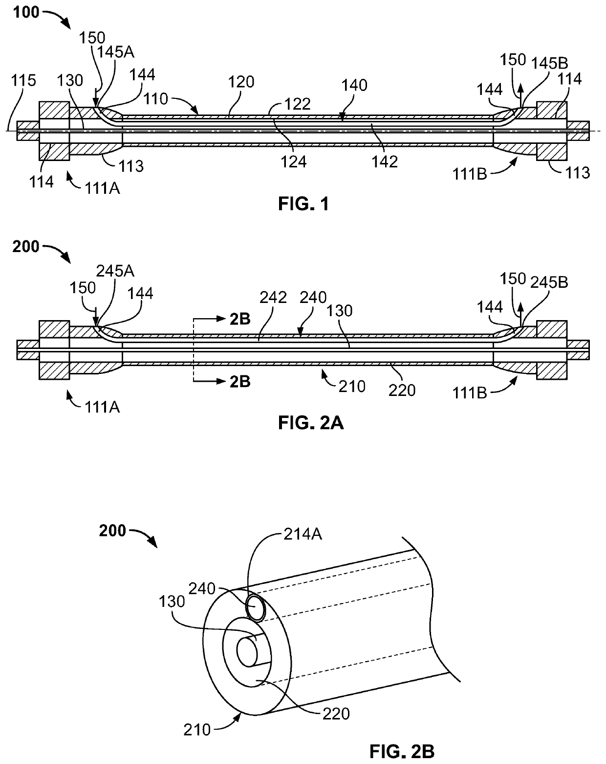
[0062]Referring now to the drawings, as shown in FIG. 1, cable 100 may be an optical fiber cable including sheath or jacket 110, optical fiber 130, which is formed from a core and a cladding (not shown), and illumination element 140. Each of fiber 130 and illumination element 140 may be disposed within elongated central bore 120 defined by jacket 110. Cable 100 may include opposing cable connectors 111A, 111B at opposing ends of the cable, and elongated central bore 120 may extend between the cable connectors along curvilinear central axis 115 defined by jacket 110. In some arrangements, the central axis may be linear. As in the example shown, cable connectors 111A, 111B may be ST optical fiber connectors, although other connector types may be utilized as described further herein. Jacket 110 may be but is not limited to being made of poly vinyl chloride (PVC) such that the jacket may be elastically flexible. Jacket 110 may have outer surface 122 and inner surface 124 spaced from the...


PUM


Abstract

A cable device includes an elongated transmission member that defines a central axis, outer cover, and illumination element. The outer cover has an outer surface and a bore along its length. The illumination element extends in a direction parallel to the central axis and along a length of the transmission member. The illumination element has first and second exposed portions extending through separated openings of the outer surface of the outer cover. Each of first and second cross-sections of the respective first and second exposed portions define respective first and second illumination element central axes extending through the cross-sections in one or more directions transverse to the central axis of the transmission member. The illumination element is configured to convey a given light such that the given light that enters the first exposed portion of the illumination element exits the second exposed portion of the illumination element.

Description

CROSS-REFERENCE TO RELATED APPLICATION[0001]The present application claims the benefit of the filing date of U.S. Provisional Patent Application No. 62 / 459,915 filed Feb. 16, 2017, the disclosure of which is hereby incorporated herein by reference.FIELD OF THE TECHNOLOGY[0002]The present technology relates generally to optical and electrical connectors, and in particular relates to the determination of the connections of such devices.BACKGROUND OF THE TECHNOLOGY[0003]Optical fibers and electrical wires are optically or electrically connected to respective opposing optical fibers and electrical wires to convey signals between the respective connected fibers and wires which may occur in the operation of data storage and transmission devices. Such optical fibers and electrical wires, or other such cables, are often of considerable length and are often clustered together with a plurality of like fibers or wires.[0004]Technicians or other professionals working with such fibers and wires ...

Claims


Application Information

Patent Timeline
Patent Type & Authority Patents(United States)
IPC IPC(8): G02B6/44H02G15/192H02G15/02F21V8/00
CPCG02B6/4452H02G15/192G02B6/447H02G15/02G02B6/0008H02G2200/20G02B6/44G02B6/0006G02B6/562
Inventor TAKEUCHI, KENICHIROLU, HAIGUANG
Owner GOFOTON HLDG
Why Eureka
Try Eureka