Disposable inflator

a technology of inflators and inflators, which is applied in the field of inflators, can solve the problems that the user is unable to easily rearm the inflator, and achieve the effect of convenient replacement and easy removal of the inflator

Active Publication Date: 2020-08-04
HALKEY ROBERTS CORP
View PDF61 Cites 6 Cited by
  • Summary
  • Abstract
  • Description
  • Claims
  • Application Information

AI Technical Summary

Benefits of technology

[0021]The invention further comprises a manifold assembly for an inflator that facilitates easy replacement of the inflator (or for routine maintenance) of the inflator is such a manner that the user may remove spent inflator and install a new one. In one embodiment of the manifold assembly, the spent inflator may be easily removed but not reinstalled, thereby assuring that the user actually installs a new inflator in its stead and does not simply reinstall the spent inflator.

Problems solved by technology

Further, the design of the disposable inflator of the invention is such that rearming a spent inflator is rendered nearly impossible by a user to thereby minimize any attempt by the user to try to rearm it instead of disposing of it and installing a new one on the inflatable.

Method used


Image

  • Disposable inflator
  • Disposable inflator
  • Disposable inflator

Examples


first embodiment

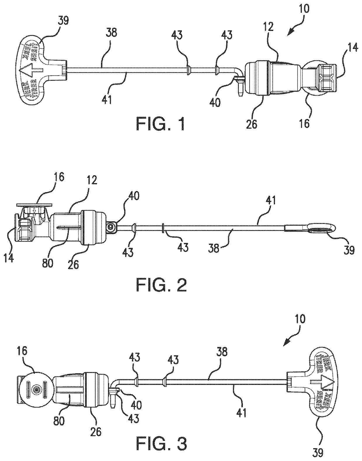
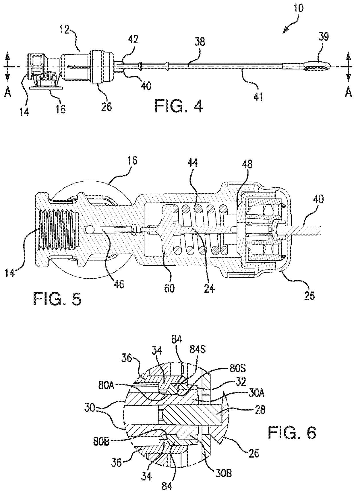
[0024]FIGS. 1-4 are front, right side, bottom and left side views of the inflator of the invention;

[0025]FIGS. 5 and 6 are cross-sectional views of the inflator of the invention;

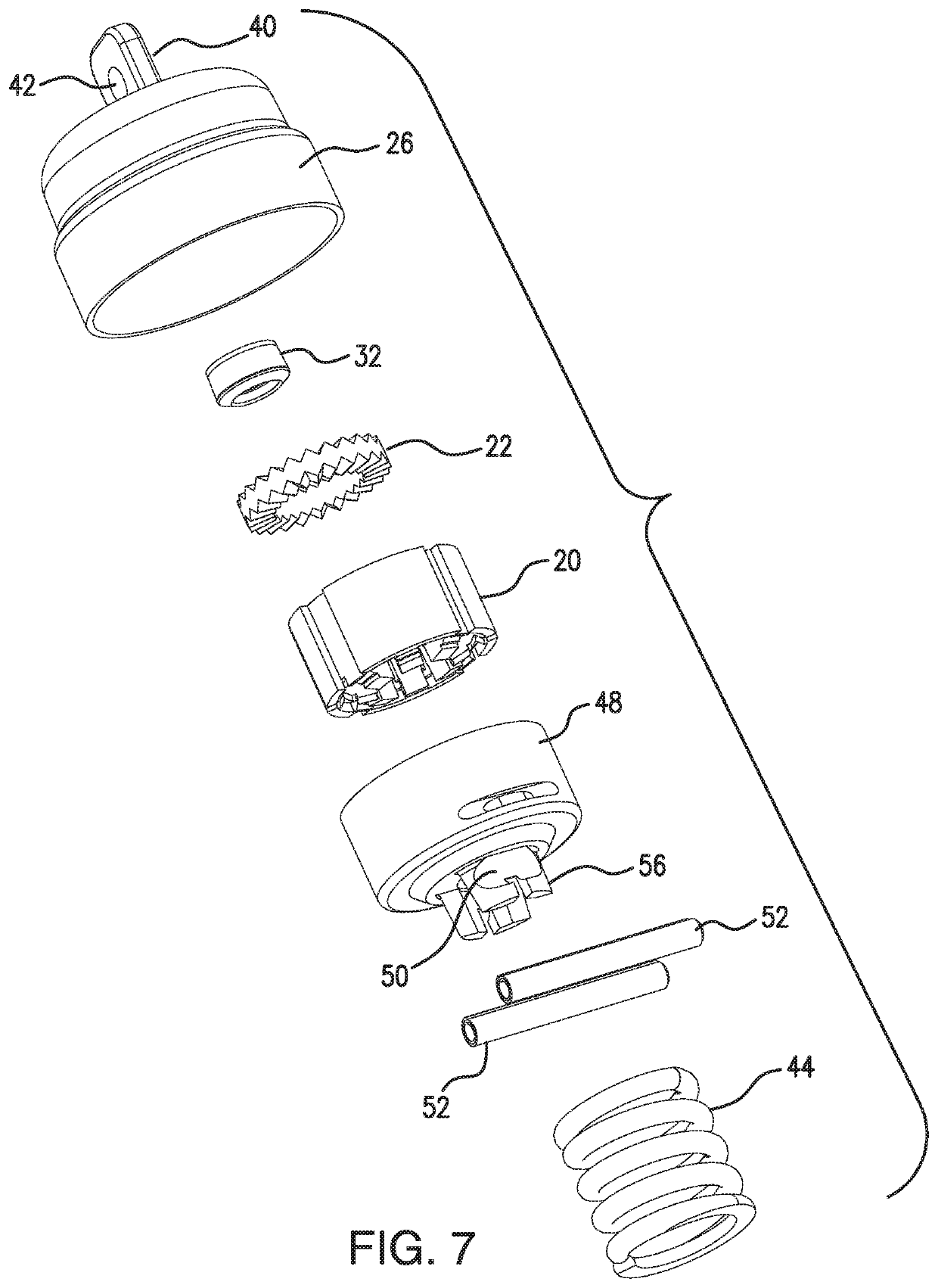
[0026]FIGS. 7 and 8 are exploded views of the inflator of the invention;

[0027]FIGS. 9 and 10 illustrate the bobbin housing of the inflator of the invention;

[0028]FIGS. 11 and 12 illustrate the body of the inflator of the invention;

[0029]FIG. 13 is a partially cut-away cross-sectional view of the ring seat of the inflator of the invention;

[0030]FIGS. 14 and 15 illustrate the actuator and FIG. 16 illustrates the pierce pin of the inflator of the invention; and

[0031]FIGS. 17-22 illustrate the first embodiment of the manifold assembly of the inflator of the invention.

second embodiment

[0032]FIG. 23 is a cross-sectional view of the inflator of the invention;

[0033]FIG. 24 is an exploded view of FIG. 23;

[0034]FIGS. 25 and 26 illustrate the bobbin housing of the second embodiment of the inflator of the invention;

third embodiment

[0035]FIGS. 27 and 28 are cross-sectional views of the inflator of the invention;

[0036]FIGS. 29 and 30 are top views of the third embodiment of the inflator of the invention;

[0037]FIG. 31 is an exploded view of the third embodiment of the inflator of the invention;

[0038]FIG. 32 is an exploded, perspective view of the see-through lens that seals the indicator window to prevent water from entering the window;

[0039]FIG. 33 is an enlarged perspective view of the see-through lens;

[0040]FIG. 34 is a side view of one embodiment of manifold assembly of the invention;

[0041]FIG. 35 is a side view of the manifold;

[0042]FIG. 36 is a perspective view of the manifold;

[0043]FIGS. 37 and 38 are perspective views of FIG. 34;

[0044]FIGS. 39 and 40 are elevational views of the manifold assembly;

[0045]FIG. 41 is an elevational view of the manifold assembly installed to the manifold;

[0046]FIGS. 42 and 43 are perspective views of the removal key intended for use with the manifold assembly of FIGS. 34 and ...


PUM


Abstract

An inflator including in combination, an inflator body having at one end an input for receiving the neck of a gas cartridge, a manifold assembly intended to be fluidly connected to an inflatable, a combination automatic and manual actuator assembly including a spring-loaded actuator including a pierce pin for fracturing a frangible seal of the gas cartridge, a bobbin with a dissolvable pill that retains the spring-loaded actuator in a cocked position by an annular ring seat that engages the bobbin and a hood connected onto the end of the inflator body, the hood including an inwardly-extending tab that engages the actuator to securely retain the hood onto the end of the inflator body by means of the inwardly-extending tab being grasped by the forked end of the actuator.

Description

CROSS-REFERENCE TO RELATED INVENTIONS[0001]This application claims the benefit of provisional application Nos. 62 / 684,725, filed Jun. 13, 2018 and 62 / 693,022, filed Jul. 2, 2018, the disclosures of which are incorporated by reference herein.BACKGROUND OF THE INVENTIONField of the Invention[0002]This invention relates to automatic inflators for inflatable articles such as life rafts, life vests, and the like. More particularly, this invention relates to inflators that are actuated automatically upon immersion in water or manually.Description of the Background Art[0003]Presently, there exists many types of inflators designed to inflate inflatable articles such as personal floatation devices (life vests, rings and horseshoes), life rafts, buoys and emergency signaling equipment. Manual inflators typically comprise a body for receiving the neck of a cartridge of compressed gas such as carbon dioxide. A reciprocating pierce pin is disposed within the body of the inflator for piercing the...

Claims


Application Information

Patent Timeline
Patent Type & Authority Patents(United States)
IPC IPC(8): B63C9/19B63C9/00
CPCB63C9/19B63C2009/007B63C2009/0058B63C9/24B63C2009/0035
Inventor FAWCETT, LYMAN
Owner HALKEY ROBERTS CORP
Why Eureka
Try Eureka