Electric toothbrush with an illumination ring

a technology of illumination rings and electric toothbrushes, applied in the field of electric toothbrushes, can solve the problem that the indicator cannot be seen by the user

Active Publication Date: 2020-08-18
COLGATE PALMOLIVE CO +1
View PDF10 Cites 9 Cited by
  • Summary
  • Abstract
  • Description
  • Claims
  • Application Information

AI Technical Summary

Benefits of technology

[0016]According to the electric toothbrush of the present invention, the user can see the indicator, which is the illumination ring, regardless of the holding angle of the electric toothbrush.

Problems solved by technology

The prior art electric toothbrush has a problem that the indicator cannot be viewed by the user, as explained above.

Method used


Image

  • Electric toothbrush with an illumination ring
  • Electric toothbrush with an illumination ring
  • Electric toothbrush with an illumination ring

Examples


Embodiment Construction

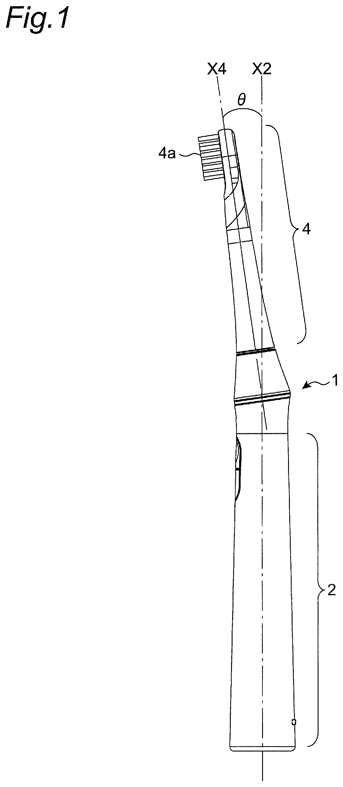
[0032]Referring to FIG. 1, an electric toothbrush 1 according to an embodiment of the present invention is shown. The electric toothbrush 1 has a grip portion 2 and a brush portion 4. An axis X4 of the brush portion 4 is angled or inclined a predetermined angle θ, such as for example but not limited to between about 6 and about 10 degrees, most preferably about 8 degrees, with respect to an axis X2 of the grip portion 2 so that a bristle portion 4a of the brush portion 4 can be easily held against a user's tooth when the grip portion 2 is held by the user proximate the user's mouth. As will be discussed below, the axis X4 and the axis X2 can be considered to be defined by the upper cylinder portion 42a and the lower cylinder portion 42b of the stem joint 42, respectively, in certain embodiments.

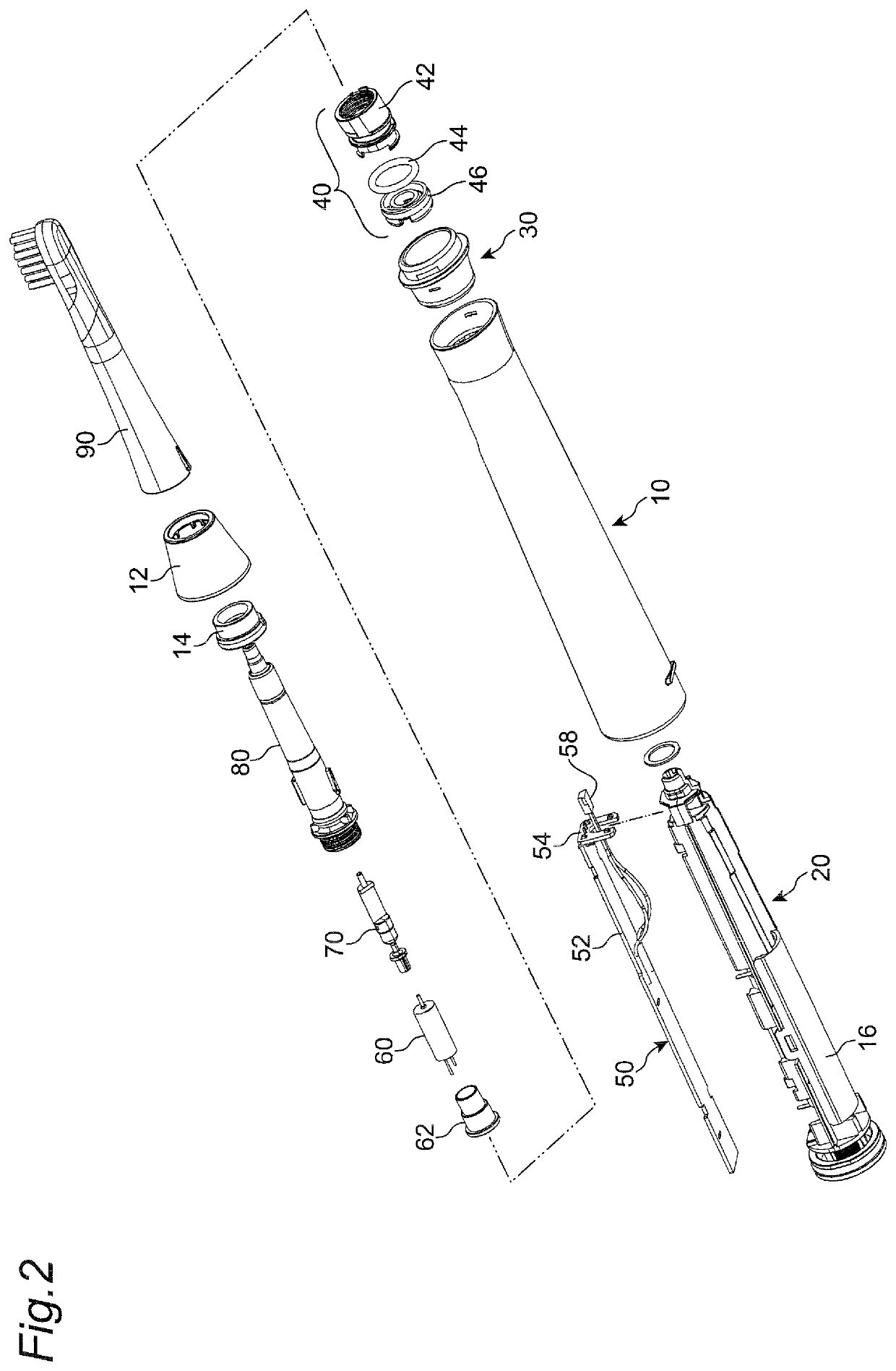
[0033]Referring to FIG. 2, an exploded view of the electric toothbrush 1 is shown. The grip portion 2 of the electric toothbrush 1 includes an elongated body cover 10, a chassis 20, a battery...


PUM

PropertyMeasurementUnit
angleaaaaaaaaaa
angleaaaaaaaaaa
angleaaaaaaaaaa

Abstract

An electric toothbrush includes a grip portion, a brush portion on which a replaceable toothbrush is mounted, and an illumination ring between the grip portion and the brush portion. The brush portion is inclined with respect to the grip portion. The illumination ring is provided around the toothbrush, so that a user can view the illumination ring no matter what angle he / she is holding the toothbrush.

Description

CROSS-REFERENCE TO RELATED PATENT APPLICATIONS[0001]This application claims the benefit of priority to Japanese Patent Application Serial No. 2016-051473, filed Mar. 15, 2016, the entirety of which is incorporated herein by reference.BACKGROUND OF THE INVENTIONField of the Invention[0002]The present invention relates to an electric toothbrush having a grip portion and a brush portion, and more particularly, to the structure of the electric toothbrush.Description of Related Art[0003]The electric toothbrush in the market has the grip portion and the brush portion with an indicator located in the grip portion. Also, the electric toothbrush in the market has the brush portion angled or inclined with respect to the grip portion. Such an electric toothbrush is disclosed, for example, in US Patent Publication No. 2011-0056033 (corresponding to Japanese Patent Publication No. 2009-268828).[0004]According to US Patent Publication No. 2011-0056033, the indicator is provided on only one side o...

Claims


Application Information

Patent Timeline
Patent Type & Authority Patents(United States)
IPC IPC(8): A46B15/00A61C17/22
CPCA61C17/221A61C17/225A46B15/0036A46B15/0044A46B2200/1066
Inventor KATANO, MAMORUNAKAMORI, HIROSHI
Owner COLGATE PALMOLIVE CO
Why Eureka
Try Eureka