Panel cart

Active Publication Date: 2020-08-25
SUNG MENG I
View PDF20 Cites 1 Cited by
  • Summary
  • Abstract
  • Description
  • Claims
  • Application Information

AI Technical Summary

Benefits of technology

[0006]In an example, the locking member includes an engaging head at an end thereof adjacent to the positioning seat. The locking member includes a pull handle at another end thereof opposite to the engaging head. The engaging head and the pull handle extend beyond two opposite ends of the outer tube, respectively. A wider portion and a narrower portion are disposed between the engaging head and the pull handle. The narrower portion has a width smaller than a width of the wider portion. The wider portion is adjacent

Problems solved by technology

However, when the panels are moved from the vehicle onto a working table by manpower, at least two persons are required for the laborsome work.
When a cart is used to transport the panels, the panels cannot be placed flatly.
A person cannot easily turn the panels having a relatively large area.
Furthermore, the vehicle

Method used


Image

  • Panel cart
  • Panel cart
  • Panel cart

Examples


Embodiment Construction

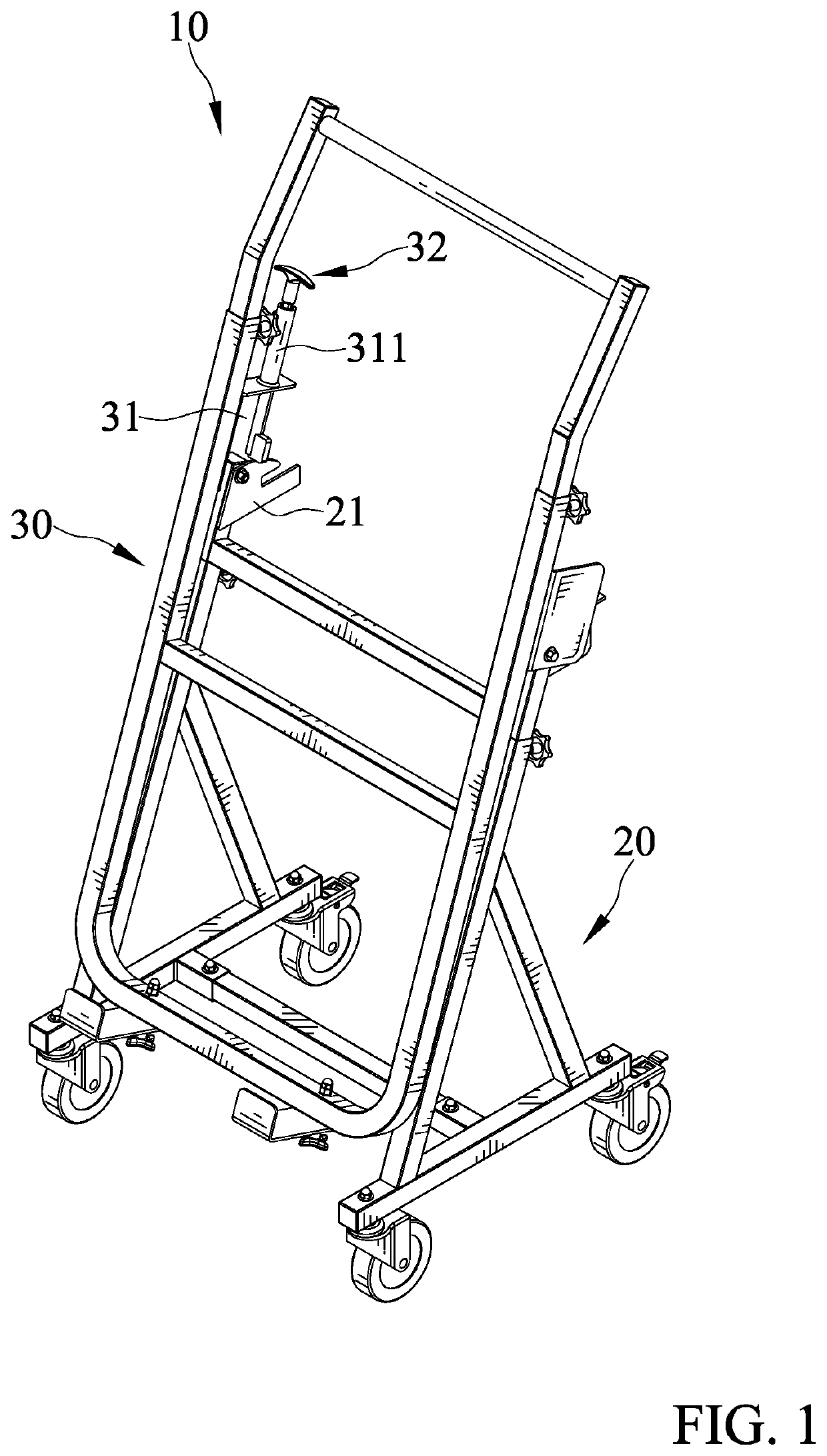
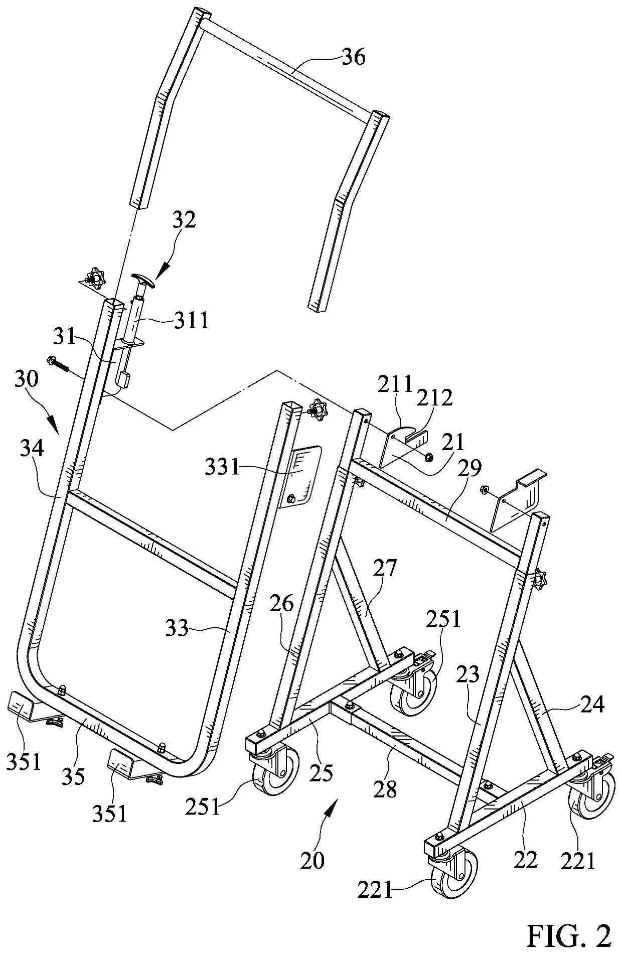
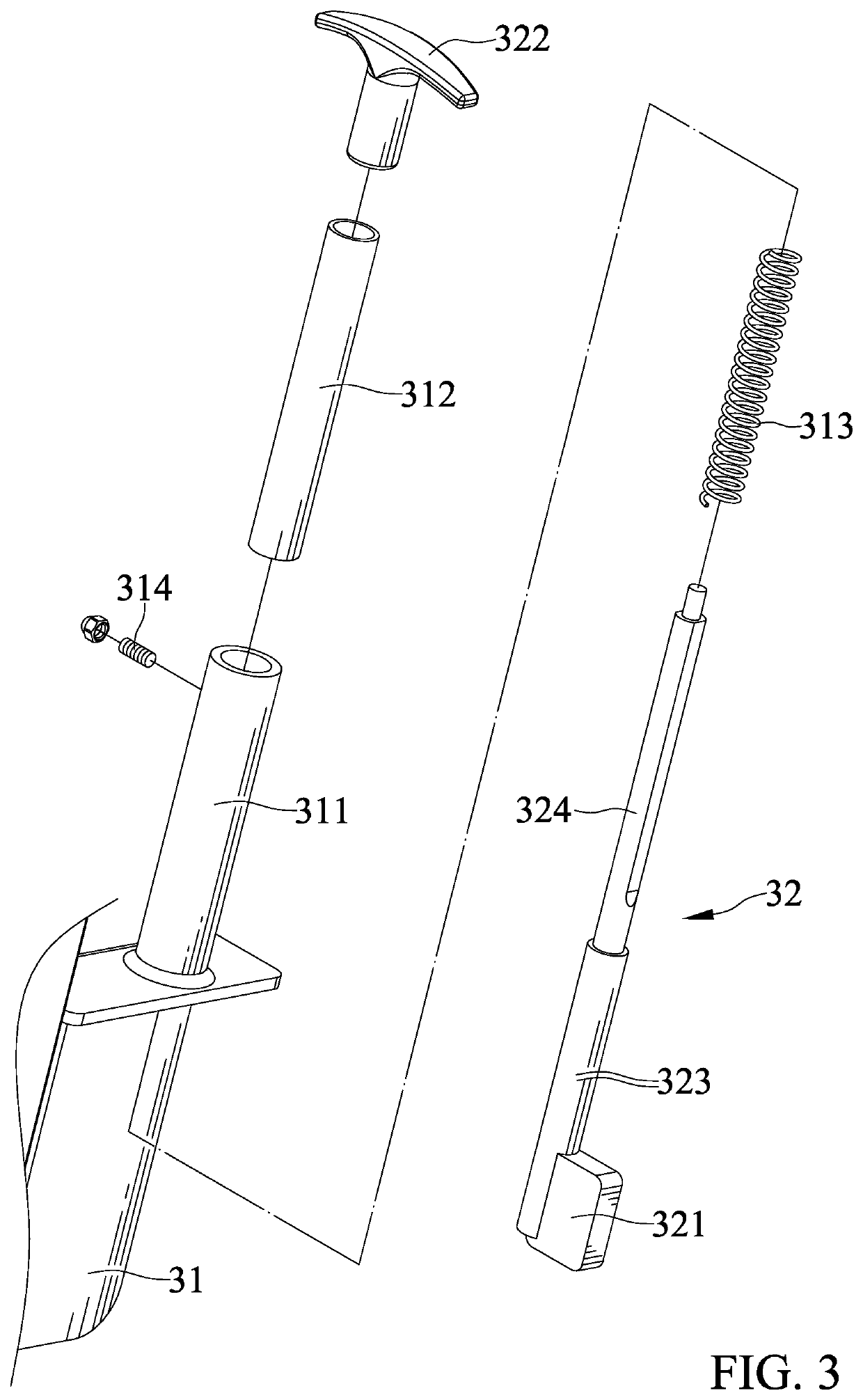
[0019]With reference to FIGS. 1-3, a panel cart 10 of an embodiment according to the present invention includes a base frame 20 and a supporting frame 30. The base frame 20 includes a positioning seat 21. The positioning seat 21 includes an outer surface having a sliding portion 211 and an engaging slot 212 contiguous to the sliding portion 211. The sliding portion 211 is arcuate.

[0020]The base frame 20 includes a first bottom beam 22, a first vertical beam 23, and a first supporting beam 24. Two first casters 221 are mounted to two opposite ends of the first bottom beam 22. A first end of the first vertical beam 23 is connected to the first bottom beam 22. An end of the first supporting beam 24 is connected between the first end and a second end of the first vertical beam 23. The basis frame 20 further includes a second bottom beam 25, a second vertical beam 26, and a second supporting beam 27. The second bottom beam 25 is parallel to the first bottom beam 22. Two second casters 25...


PUM


Abstract

A panel cart includes a base frame and a supporting frame. The base frame includes a positioning seat. The positioning seat includes an outer surface having a sliding portion and an engaging slot contiguous to the sliding portion. A supporting frame is pivotably mounted to the base frame and pivotable between a folding position and an extended position about a pivotal axis. The supporting frame includes a locking seat and a locking member slidably mounted to the locking seat. The locking member remains in contact with the positioning seat. The locking member abuts against the sliding portion when the supporting frame is in the folding position. The locking member engages with the engaging groove when the supporting frame is in the extended position.

Description


Claims


Application Information

Patent Timeline
Owner SUNG MENG I
Why Eureka
Try Eureka