Scan driver and display device having the same

a display device and scanner technology, applied in the direction of static storage, digital storage, instruments, etc., can solve the problems of abnormal output of scan signals, display defect may be displayed on a display panel, display defect of the display device may improve, etc., to achieve the effect of improving the display defect of the display devi

Active Publication Date: 2020-08-25
SAMSUNG DISPLAY CO LTD
View PDF8 Cites 0 Cited by
  • Summary
  • Abstract
  • Description
  • Claims
  • Application Information

AI Technical Summary

Benefits of technology

[0028]Therefore, the scan driver and the display device according to some example embodiments may prevent or reduce instances of the abnormal scan signal by including the block circuit that receives the scan control signal and block the scan control signal when the scan control signal has the voltage level lower than the first reference voltage and higher than the second reference voltage. Thus, a display defect of the display device may improve.

Problems solved by technology

When the scan control signal having an abnormal range is provided to the scan driver, the scan signal outputs in an abnormal timing.
Thus, a display defect may be displayed on a display panel.
Thus, a display defect of the display device may improve.

Method used


Image

  • Scan driver and display device having the same
  • Scan driver and display device having the same
  • Scan driver and display device having the same

Examples


Embodiment Construction

[0043]Hereinafter, aspects of some example embodiments of the present invention will be explained in more detail with reference to the accompanying drawings.

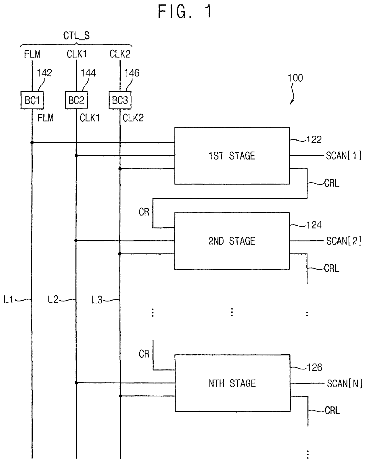
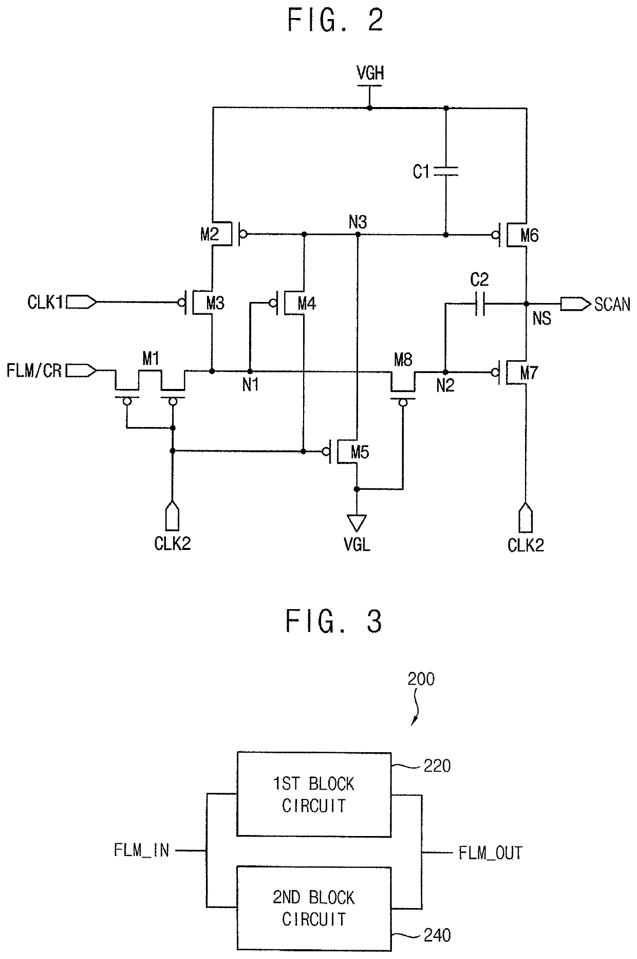
[0044]FIG. 1 is a block diagram illustrating a scan driver according to some example embodiments and FIG. 2 is a circuit diagram illustrating an example of a stage included in the scan driver of FIG. 1.

[0045]Referring to FIG. 1, a scan driver 100 may include a plurality of stages 122, 124, 126 and block circuits 142, 144, 146. Each of the stages 122, 124, 126 may be dependently coupled and sequentially output scan signals SCAN[1], SCAN[2], SCAN[3]. The scan signals SCAN[1], SCAN[2], SCAN[3] may be provided to pixels of a display panel through scan lines formed on the display panel.

[0046]Each of the stages 122, 124, 125 may receive a scan control signal CTL_S. The scan control signal CTL_S may include a start signal and at least one clock signal. For example, the stages 122, 124, 126 of FIG. 1 may receive the start signal FLM, a ...


PUM


Abstract

A scan driver includes: a blocking circuit configured to receive a scan control signal and to block the scan control signal lower than a predetermined first reference voltage and higher than a predetermined second reference voltage, wherein the second reference voltage is higher than the first reference voltage; and a plurality of stages configured to output scan signals in response to the scan control signal, wherein the blocking circuit includes: a first block circuit configured to block the scan control signal lower than the first reference voltage; and a second block circuit configured to block the scan control signal higher than the second reference voltage.

Description

CROSS-REFERENCE TO RELATED APPLICATION[0001]This application claims priority to and the benefit of Korean Patent Application No. 10-2018-0038174, filed on Apr. 2, 2018 in the Korean Intellectual Property Office (KIPO), the entire content of which is incorporated herein in its entirety by reference.BACKGROUND1. Field[0002]Aspects of some example embodiments relate generally to a scan driver and a display device having the same.2. Description of the Related Art[0003]Flat panel display (FPD) devices are widely used as a display device for electronic devices because FPD devices are relatively lightweight and thin compared to cathode-ray tube (CRT) display devices. Examples of FPD devices are liquid crystal display (LCD) devices, field emission display (FED) devices, plasma display panel (PDP) devices, and organic light emitting display (OLED) devices. The OLED devices have been spotlighted as next-generation display devices because OLED devices have various characteristics such as a rel...

Claims


Application Information

Patent Timeline
Patent Type & Authority Patents(United States)
IPC IPC(8): G09G3/3266
CPCG09G3/3266G09G2310/08G09G2310/061G09G2310/0286G11C19/28G09G2330/12G09G2330/08G09G2300/0842G09G2230/00
Inventor LEE, HYO-CHULKIM, CHOLHOKIM, HONGBOCHAI, YOONJUNG
Owner SAMSUNG DISPLAY CO LTD
Why Eureka
Try Eureka