Rotational driver

a technology of rotational action and needle driver, which is applied in the field of surgical suturing devices, can solve the problems of affecting the suturing procedure, affecting the patient's recovery, and damage to adjacent tissues or even organs, so as to reduce the risk of damage to peripheral tissues, ease the suturing procedure, and reduce the number of maneuvers

Active Publication Date: 2020-09-29
ERGOSURGICAL GRP CORP
View PDF20 Cites 1 Cited by
  • Summary
  • Abstract
  • Description
  • Claims
  • Application Information

AI Technical Summary

Benefits of technology

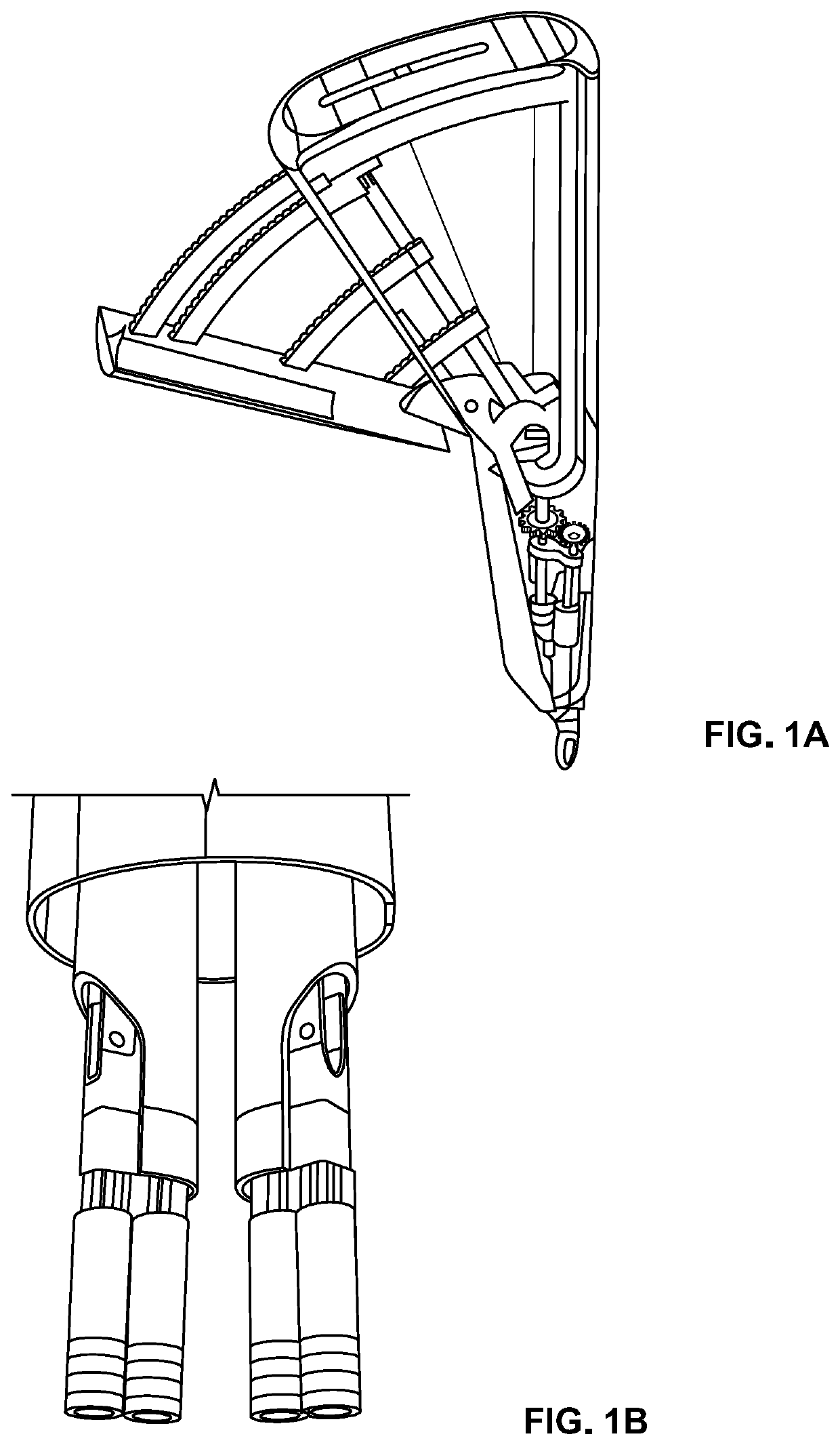
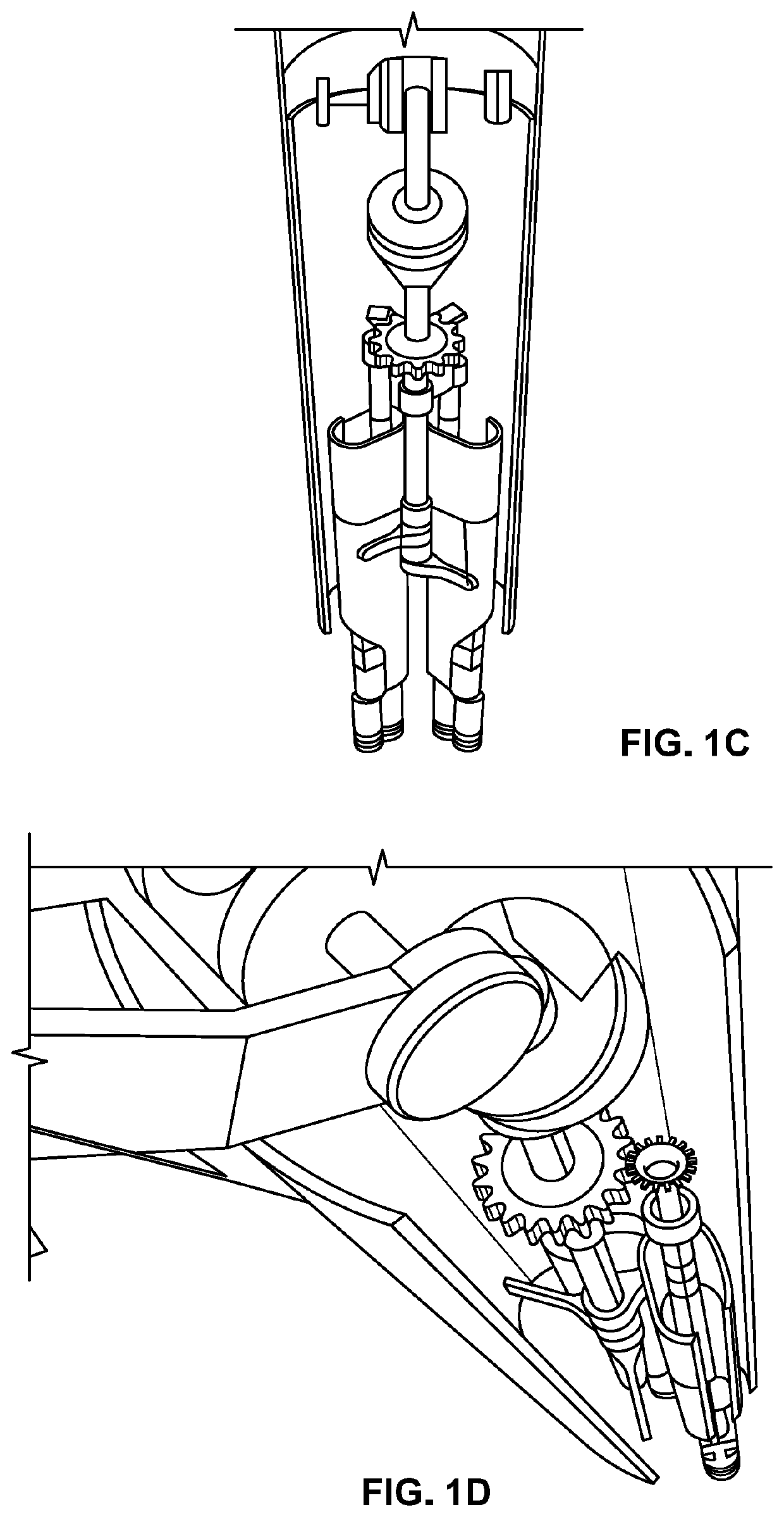
[0011]The disclosed invention provides an effective suturing device including a needle that enhances the maneuvering and safety of suturing procedures, more particularly the process of handling the needle. The rotational driver comprises a interactive portion, wherein each interactive portion comprises a first extended member and a second extended member, a rotational system, wherein said first extended member comprises a first distal end, a first proximal end and a first main extended member body, wherein said first main member body in between said first distal end and said first proximal end, wherein said first distal end comprises a first contact distal end, wherein said second extended member comprises a second distal end, a second proximal end and a second main member body, wherein said second main member body is between said second distal end and said second proximal end, wherein said second distal end comprises a second contact distal end, wherein said rotational system comprises a rotational actuator mechanically coupled to at least an action transmitter mechanism, wherein said action transmitter mechanism is mechanically connected to said first extended member providing rotating action upon said first distal end; and wherein said first distal end and said second distal end contact each other. Further the device comprises a distal end motion system comprising mechanical means to provide displacement of said second distal end with respect to said first distal end (or vice versa) and wherein said distal end displacement exert compressing force against the other distal end, wherein said compressing force is concentrated at said first contact distal end and said second contact distal. It has to be understood that the contact between distal ends may be an oblique contacts or a flat contact.
[0012]Another object of the present invention is to provide a mechanism to drive the needle in different angles. The present suturing device comprises disposable or not disposable tips at the distal end. Said tips is configured at the needle contact area to be shape with angular or predetermined angular configurations. The distal end maintain the needle tightly fixed to the needle driver in order to have a best control over the needle and the movements related to the suturing process. The present configuration permits the user to position the suturing needle at the exact angle at which the suturing material has to be inserted into the tissue.
[0013]Another object of the present invention is to provide a needle configured to match a distal end tip in order to be drove in different angles. The present suturing device comprises needle comprising an outer surface that matches the distal end tip in order to assists the angular driving process of the needle. Said tips is configured at the needle contact area to be shape in a manner that matches the needle contour. The distal end maintain the needle tightly fixed to the needle driver in order to have a best control over the needle and the movements related to the suturing process. The present configuration permits the user to position the suturing needle at the exact angle at which the suturing material has to be inserted into the tissue.
[0015]None of the prior art considered above, taken either simply or in combination teaches the use of a suturing needle driver suitable to left and right handed users and comprising a pull locking mechanism and a rotational mechanism. In light of the foregoing, it will be appreciated that what is needed in the art is a suturing needle driver lacking of handedness and combining a pull locking mechanism and a rotational mechanism. Thus, the object of the present invention is to provide a surgical device that eases the suturing procedure associated with deep, restricted areas.
[0016]Another object of the present invention is to provide a surgical suturing needle driver that permits to grasp, secure and rotate a curved surgical needle without requiring a rotational motion at the surgeon's wrist.
[0017]It is the object of the present invention to provide a surgical suturing needle driver which incorporates a distal end that secures the needle to the needle driver and permits to diminish the number of maneuvers actually needed for performing the surgical suturing process, reducing the risk of damaging peripheral tissues.

Problems solved by technology

It is undoubted that each and every step on any surgical procedure is of great importance and could cause negative consequences for the patient if it is inadequately performed.
The suturing procedure, in particular, could end in serious consequences for the patient if negligently conducted, causing damages to adjacent tissues or even organs.
It is known that the suturing procedure consumes a considerable amount of time of the surgical treatment.
However, one of the generally unattended deficiencies of the available needle drivers is the angular position of the needle.
This increases the risks of negative outcomes for patients from wrong needle driver maneuverings and problem with reaching small, deep and restricted areas.

Method used


Image

  • Rotational driver
  • Rotational driver
  • Rotational driver

Examples


Embodiment Construction

[0033]To provide an overall understanding of the invention, certain illustrative embodiments and examples will now be described. However, it will be understood by one of ordinary skill in the art that the same or equivalent functions and sequences may be accomplished by different embodiments that are also intended to be encompassed within the spirit and scope of the disclosure. The compositions, apparatuses, systems and / or methods described herein may be adapted and modified as is appropriate for the application being addressed and that those described herein may be employed in other suitable applications, and that such other additions and modifications will not depart from the scope hereof.

[0034]As used in the specification and claims, the singular forms “a”, “an” and “the” include plural references unless the context clearly dictates otherwise. For example, the term “a transaction” may include a plurality of transaction unless the context clearly dictates otherwise. As used in the...


PUM


Abstract

A rotational driver that comprises a interactive portion, wherein each interactive portion comprises a first extended member and a second extended member, a rotational system and a linear motion system, wherein the rotational driver permits a left or right handed surgeons to perform the surgical suturing procedure in a less complicated and more secure way by allowing more control over the angled suturing needle and the area to be stitched, even when the suturing area is small, deep, and / or restricted. Also the rotational driver comprises several configurations at the interactive portion ends to provide selected angles for the needle during the suturing procedure.

Description

STATEMENT REGARDING FEDERALLY SPONSORED RESEARCH AND DEVELOPMENT[0001]N / ARELATED APPLICATIONS[0002]N / ABACKGROUND OF INVENTIONField of the Invention[0003]The present invention relates generally to a surgical suturing device, more specifically, to an ergonomic Rotational Action Needle Driver which enhance the tissue suturing procedure, particularly the one performed on restricted, deep and less accessible locations, by incorporating an angled needle grasping mechanism that prevents problems associated with loss of needle control during the suturing procedure and the ones associated with prior needle driver's handedness. It also enhances the control surgeons has over the suturing needle by enabling a multiple angles rotational movement of a needle while driving the suturing needle through the tissue permitting to place the needle in the right location in order to continue the subsequent steps of the suturing cycle.Background of the Invention[0004]Surgical procedures have proliferated a...

Claims


Application Information

Patent Timeline
Patent Type & Authority Patents(United States)
IPC IPC(8): A61B17/04A61B17/00A61B17/06A61B17/062
CPCA61B17/0491A61B17/06066A61B17/062A61B17/0625A61B2017/00424A61B2017/00473A61B2017/0608A61B2017/00477A61B2017/06071A61B2017/00367A61B2017/0609
Inventor ALMODOVAR, LUIS JOSE
Owner ERGOSURGICAL GRP CORP
Why Eureka
Try Eureka