
Door guard assembly

a door guard and assembly technology, applied in the direction of wing fasteners, construction fastening devices, fastening means, etc., can solve the problems of shortfalls of existing chain door guards that are commercially available to consumers

Active Publication Date: 2020-12-15
DOHERTY PATRICK JOHN
View PDF41 Cites 2 Cited by
  • Summary
  • Abstract
  • Description
  • Claims
  • Application Information

AI Technical Summary

Benefits of technology

[0001]The present invention relates to door guard assemblies which in use can be operably connected to a hinged door and its frame to permit limited opening of the door, thus preventing unwanted entry of the door by third parties.
[0002]Door guard assemblies are locking devices that are generally referred to as door chains or door security devices, and they usually comprise a short length of chain, one end of the chain is secured to an anchor plate that is rigidly attached to a door frame and the other end of the chain being releasably engagable with a guard plate, said guard plate being rigidly attached to the door associated with the door frame. In use, the device allows the door to be opened a limited distance to confirm the identity of the caller, but prevents unwanted entry by the caller whilst the chain is engaged with the door guard plate and the door is partially opened. If required the free end of the chain may be disengaged from the guard plate allowing the door to be opened fully.
[0011]The door guard assembly described herein provides an advantage in that it is more resistant to attack by a would-be intruder, as compared to previously known door guard assemblies, as the damper absorbs a force applied to the partially opened door, when the door security device (door guard assembly) claimed herein is in use. Additionally, the use of a slidable plate to activate the door guard assembly (such that the door guard assembly is in its second operative (or standby) position) is particularly advantageous as it provides for easier activation of the device as compared to other known door guard assemblies; where, for instance, with other door guard assemblies, it may be necessary to engage a door chain end stop on a first part of the assembly with an elongate slot on a second part—such engagement which may require considerable manual dexterity.
[0023]The stop, in use, engages with the larger aperture in the plate to prevent the elongate body disengaging from the receiving means. When the receiving means comprises a first aperture adjacent a second aperture then it is the second aperture that engages the stop in use. In this way a large surface area of the plate is engaged with the stop, such that any impact force applied to the door that is not absorbed by the dampening means is transmitted to a large area of the plate thus reducing potential damage to the plate.

Problems solved by technology

Although the existing devices offer a degree of security, there are shortfalls associated with the existing chain door guards that are commercially available to consumers.

Method used


Image

  • Door guard assembly
  • Door guard assembly
  • Door guard assembly

Examples


Embodiment Construction

[0037]Specific embodiments of the invention will now be described, by way of example only, with reference to the accompanying drawings, in which:—

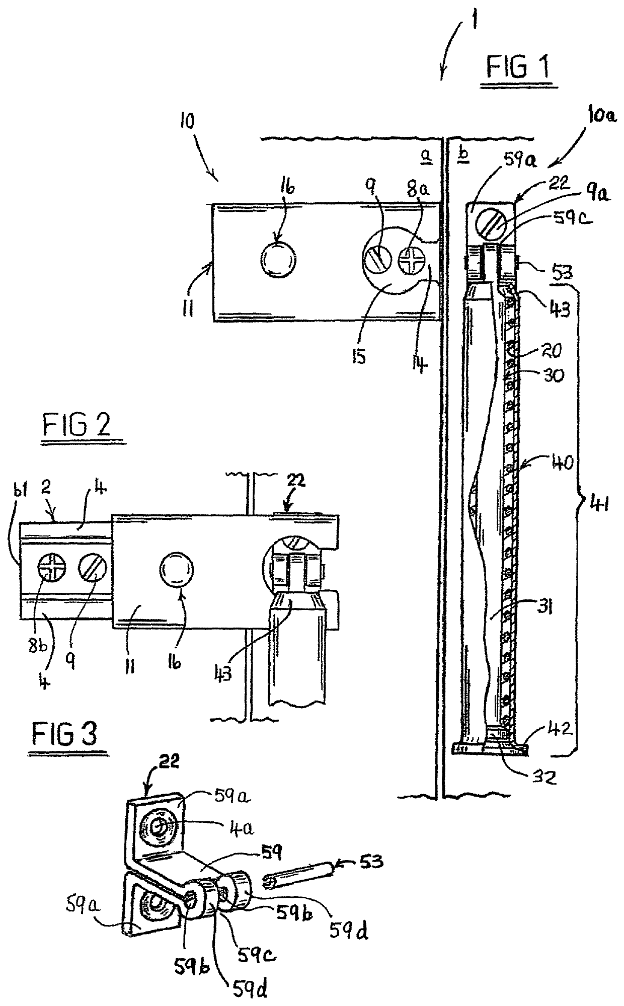
[0038]FIG. 1 illustrates a front elevation of a door guard assembly, in its first inoperative position, and includes a partial cross-sectional view, according to the present invention.

[0039]FIG. 2 illustrates a partial front elevation of the door guard assembly as illustrated in FIG. 1 wherein the assembly is in its second operative (or standby) position.

[0040]FIG. 3 illustrates a perspective view of a door frame anchor bracket for a door guard assembly according to the present invention as previously illustrated in FIG. 1.

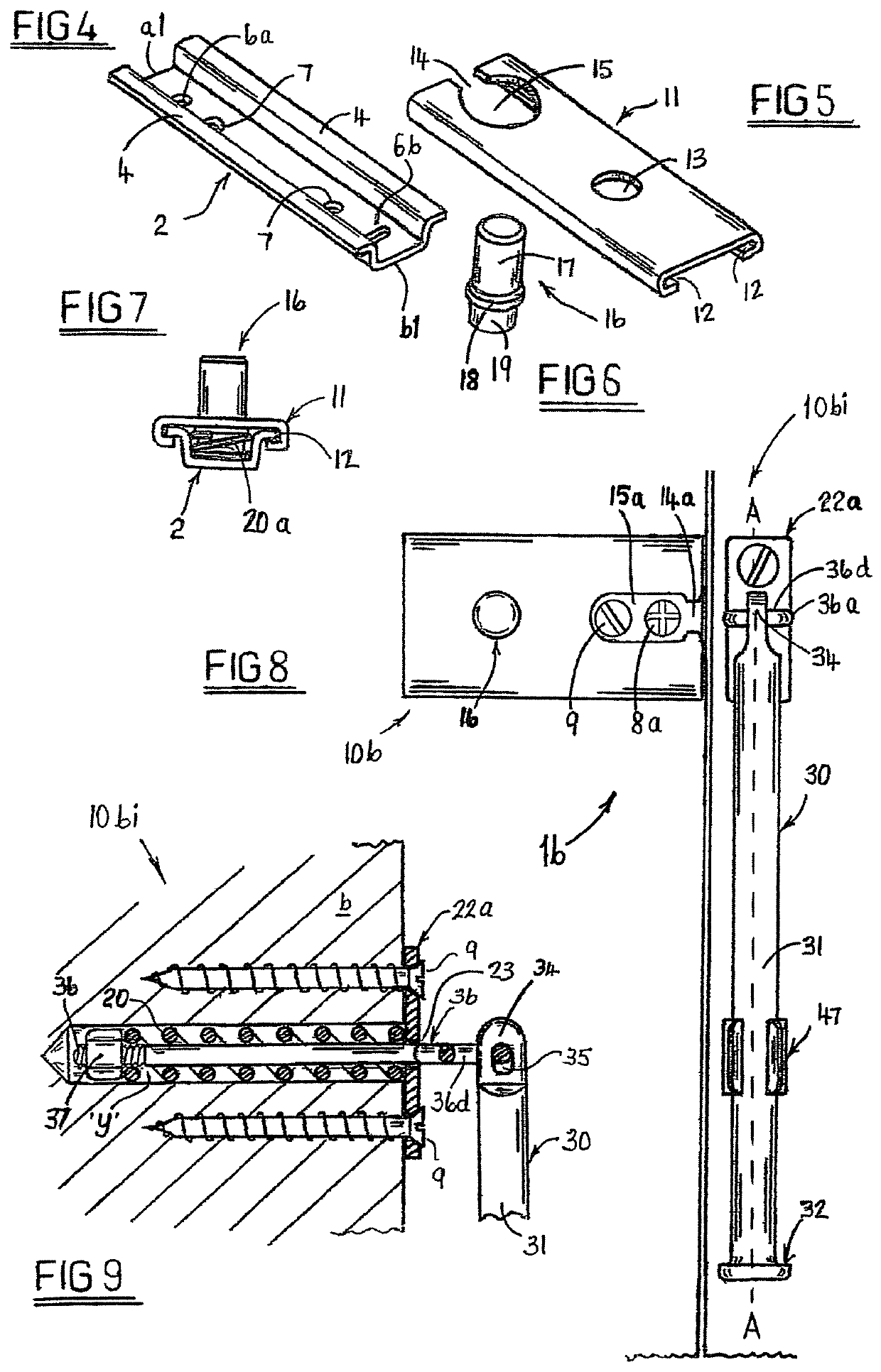
[0041]FIGS. 4 to 7 illustrate perspective views of the components that together comprise a door guard plate for a door guard assembly according to the present invention.

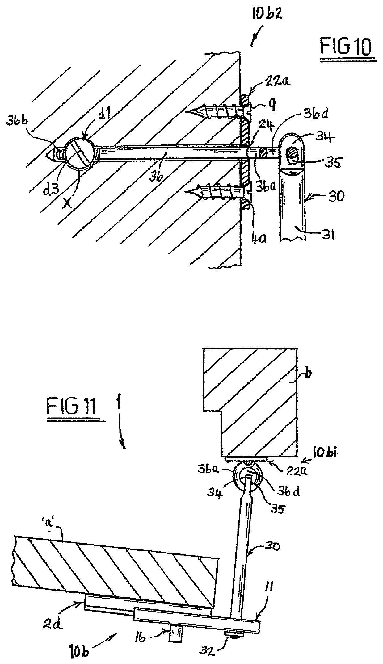
[0042]FIG. 8 illustrates a front elevation of an alternative embodiment of a door guard assembly, in its first inoperative position, according to the pre...


PUM


Abstract

A door guard assembly is provided comprising: a first part that is attachable to a door; a second part that is attachable to a door frame; an elongate member; a slidable plate that comprises a receiving means; wherein the first part and / or the second part and / or the elongate member further comprise(s) a dampening means; and, wherein the elongate member is attached to the first part or the second part and in use can be engaged with the receiving means of the plate located on the other first or second part respectively when the plate is slid into an operating position such that the receiving means engages the outer surface of the elongate member as the door is opened and the receiving means and elongate member thus limit the opening of the door, and the dampening means absorbs an impact force that may be applied to the door whose opening has been limited in this way.

Description

[0001]The present invention relates to door guard assemblies which in use can be operably connected to a hinged door and its frame to permit limited opening of the door, thus preventing unwanted entry of the door by third parties.[0002]Door guard assemblies are locking devices that are generally referred to as door chains or door security devices, and they usually comprise a short length of chain, one end of the chain is secured to an anchor plate that is rigidly attached to a door frame and the other end of the chain being releasably engagable with a guard plate, said guard plate being rigidly attached to the door associated with the door frame. In use, the device allows the door to be opened a limited distance to confirm the identity of the caller, but prevents unwanted entry by the caller whilst the chain is engaged with the door guard plate and the door is partially opened. If required the free end of the chain may be disengaged from the guard plate allowing the door to be opene...

Claims


Application Information

Patent Timeline
Patent Type & Authority Patents(United States)
IPC IPC(8): E05C17/48E05C17/04E05C17/36E05C17/30E05B17/00E05B15/04E05C17/16
CPCE05C17/48E05C17/04E05C17/365E05C17/30E05C17/166Y10T292/31E05B17/0041E05B15/04
Inventor DOHERTY, PATRICK JOHN
Owner DOHERTY PATRICK JOHN
Learn More