Rod inserter and methods of use

a technology of inserters and rods, applied in the field of spine surgery, can solve the problems of not providing flexibility in adjusting devices, leaving very little room for adjustment in accordance with patient's physiological characteristics, etc., and achieve the effect of reducing rods

Active Publication Date: 2021-03-02
ALPHATEC SPINE INC
View PDF19 Cites 0 Cited by
  • Summary
  • Abstract
  • Description
  • Claims
  • Application Information

AI Technical Summary

Benefits of technology

[0023]In some embodiments, the present invention relates to a method for reducing a rod using the above rod reducer tool used in connection with a screw extender housing secured to a screw assembly implanted into a vertebrae. The method includes inserting the screw extender housing inside the hollow shaft, translating the rod reducer tool along the screw extender housing toward the screw assembly, and rotating the rotating handle to advance the rod reducer tool toward the screw assembly, thereby reducing the rod.

Problems solved by technology

These devices do not provide flexibility when adjusting the devices either prior to, during, or after their placement into the patient.
Thus, these devices force a surgeon to utilize a specific configuration, leaving very little room for adjustment in accordance with patient's physiological characteristics and needs.

Method used


Image

  • Rod inserter and methods of use
  • Rod inserter and methods of use
  • Rod inserter and methods of use

Examples


Embodiment Construction

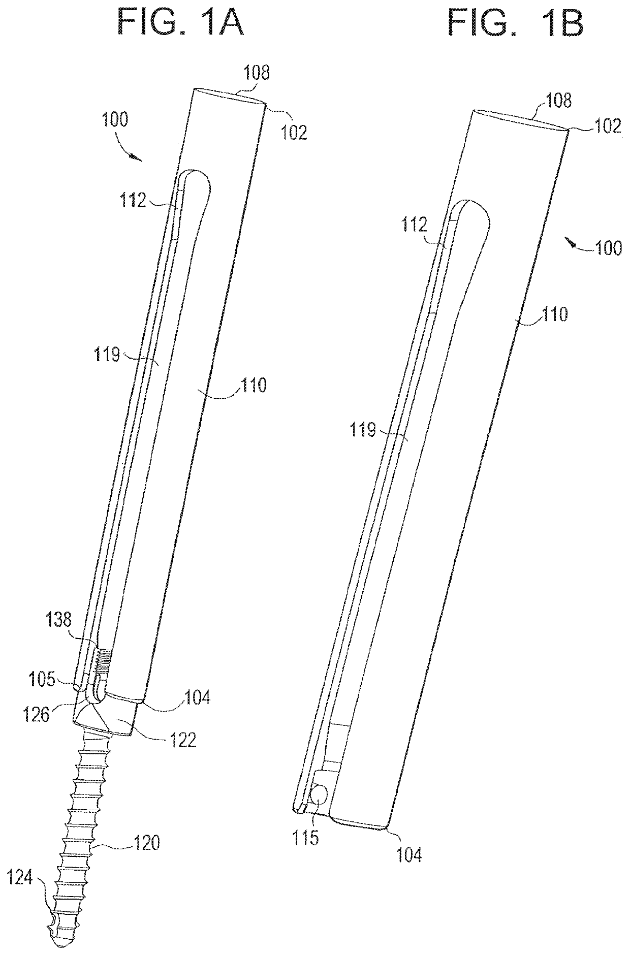
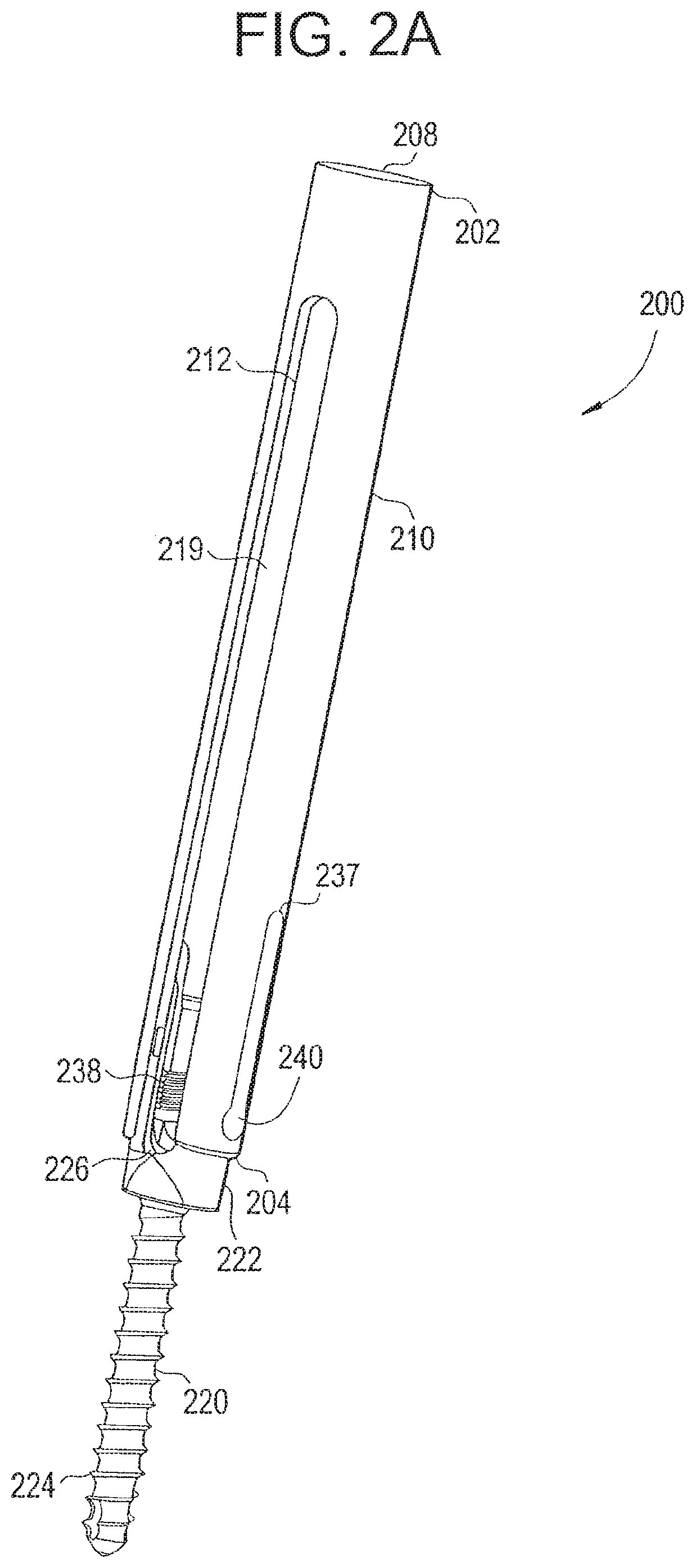
[0060]In some embodiments, the present invention allows a surgeon using conventional stab wounds to place bone screws. This is typically accomplished using a Jamshiti needle followed by progressive dilation. Once the bone has been prepared, the bone screw is implanted.

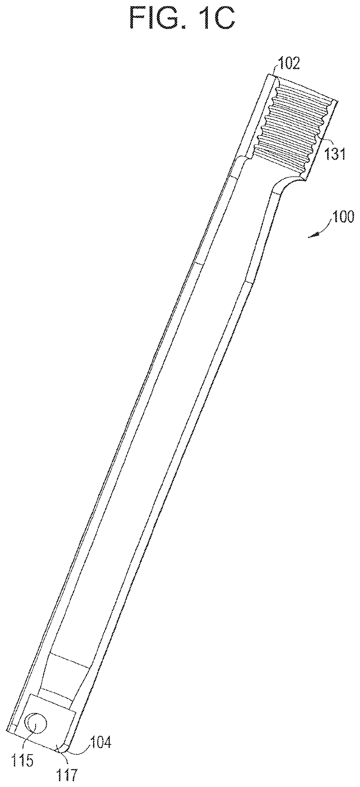
[0061]After implantation, the bone screw is manipulated for orientation by the extender. This “extender” extends out of the stab wound and allows the surgeon to control the implanted screw. Once two or more screws are implanted, the surgeon will place the wire inserters onto the screw extender. The wire components are designed to guide a wire down the axis of the screw extender. Once the desired depth is reached, the wire will exit out of the screw extender and puncture the muscle and create a path to join the adjacent bone screw.

[0062]Once the wire bridges the gap between the screws, an instrument that has been previously placed down the adjacent extender grabs the wire and pulls the distal portion of the wire to the ...


PUM


Abstract

The tool and surgical kit are configured to facilitate in-situ reattachment of a screw extender to screw is provided. The surgical kit includes a screw extender, a screw assembly and a tool. The screw extender has a channel extending from a proximal end to a distal end of the screw extender. The screw assembly includes a screw and a set screw. The screw includes a threaded shaft and a head having a pair of sidewalls spaced apart from each. The interior surface of the sidewalls is threaded. The tool includes a first and a second removable shaft, the distal ends of which are configured to respectively engage the screw and the set screw. The tool includes a main shaft, a handle and a hollow housing. The main shaft is configured to fit through the channel, and the hollow housing is configured to receive the screw extender housing.

Description

CROSS-REFERENCE TO RELATED APPLICATIONS[0001]The present application is a divisional application of U.S. patent application Ser. No. 13 / 828,573 filed on Mar. 14, 2013, which in turn is a divisional application of U.S. patent application Ser. No. 12 / 462,974 filed on Aug. 11, 2009 (now U.S. Pat. No. 8,394,109), which in turn is a continuation-in-part application of U.S. patent application Ser. No. 12 / 290,035 filed on Oct. 23, 2008 (now U.S. Pat. No. 8,469,960) which in turn claims priority to U.S. Provisional Patent Application No. 61 / 132,974 filed Jun. 23, 2008 and claims priority to U.S. Provisional Patent Application No. 61 / 000,263, filed Oct. 23, 2007, all of which are incorporated herein by reference in their entirety. The present application is a divisional application of U.S. patent application Ser. No. 13 / 828,573 filed on Mar. 14, 2013, which is also a continuation-in-part of U.S. patent application Ser. No. 12 / 290,035 filed Oct. 23, 2008, which is incorporate herein by refere...

Claims


Application Information

Patent Timeline
Patent Type & Authority Patents(United States)
IPC IPC(8): A61B17/70A61B17/88
CPCA61B17/708A61B17/7032A61B17/7082A61B17/7083A61B17/7085A61B17/7086A61B17/7091A61B17/8861A61B17/7077
Inventor HUTTON, CLARKSMITH, KETCHEN
Owner ALPHATEC SPINE INC
Why Eureka
Try Eureka