
Three dimensional printing material system and method

a three-dimensional printing and material technology, applied in the direction of solid and fluid additive manufacturing, solid waste management, water setting substance layered products, etc., can solve the problems of high cost of selective laser sintering process, slow method, and low cost of binder printing equipment, so as to improve the strength and toughness of the final article, improve the viscosity of the aqueous fluid, and improve the effect of toughness

Inactive Publication Date: 2003-08-26
3D SYST INC
View PDF53 Cites 161 Cited by
  • Summary
  • Abstract
  • Description
  • Claims
  • Application Information

AI Technical Summary

Benefits of technology

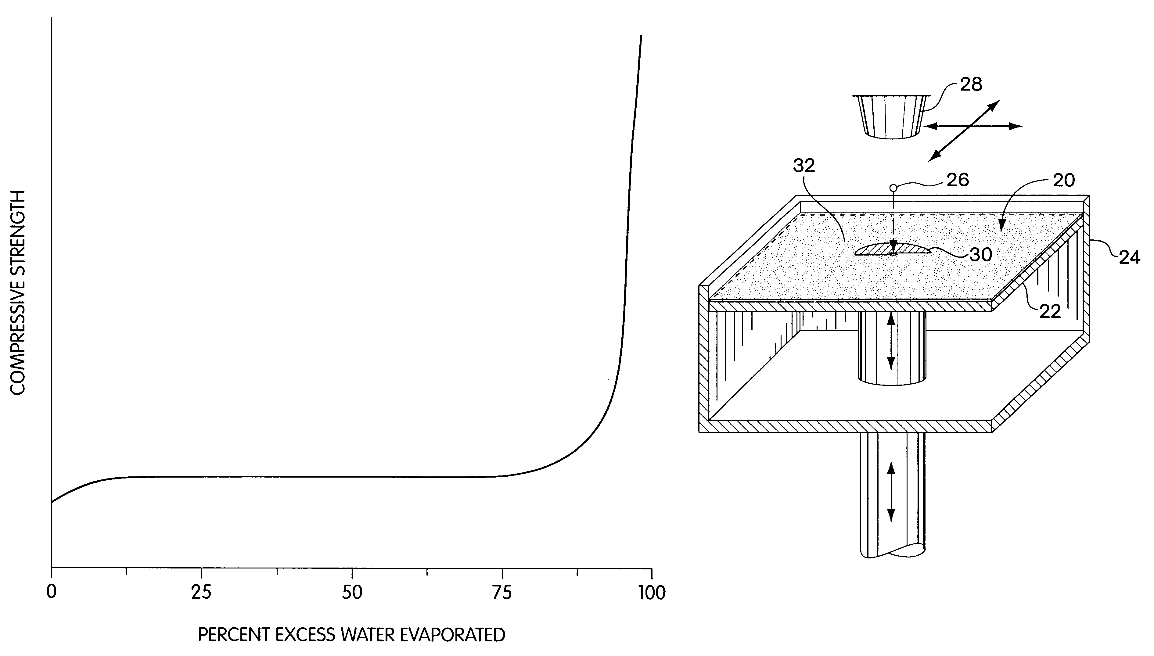
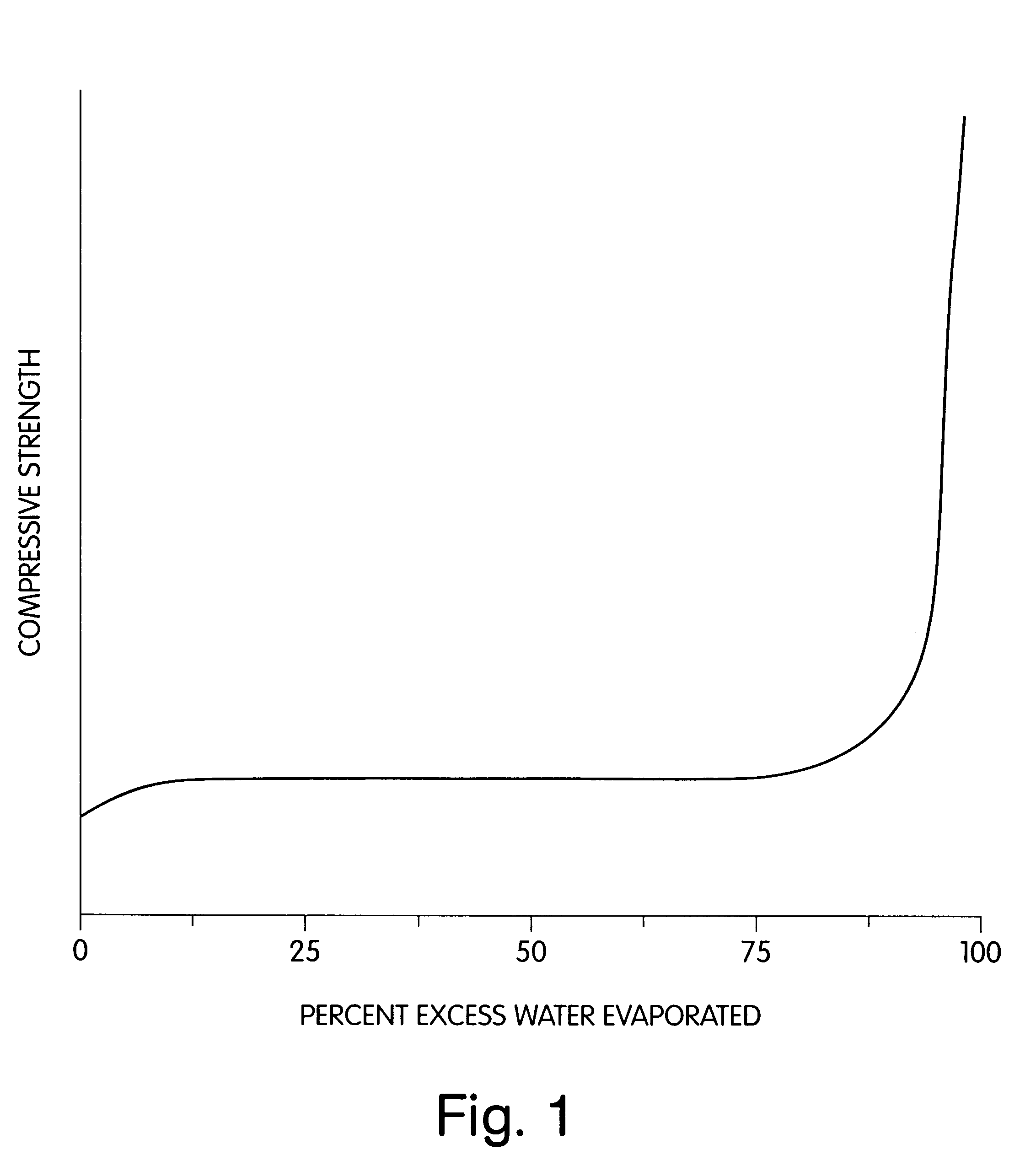
For purposes of the present invention, "aqueous fluid," as used herein, is meant to define any fluid containing sufficient water to set up the plaster contained in the particulate material, which is readily determined by those of ordinary skill in the art. In general, increasing the ratio of water to plaster increases strength of the final article. Therefore, maximizing the amount of aqueous fluid printed to the particulate material layer will generally increase the strength of the final article, but sometimes at the expense of increasing the amount and / or severity of distortions in the printed article. "Distortions," as used herein, includes, but is not limited to warping, caking, and bleeding. Consequently, the ratio of water to plaster is practically limited by several factors, including the desired speed of printing, and the acceptable amount of distortion in the final article. In theory, 100% water may be printed as the aqueous fluid --but in practice, the nozzles may clog. Therefore, it may be desirable to include various processing aids in the aqueous fluid, while maintaining a sufficient amount of water to react with the plaster. Preferably, the amount of water contained in the aqueous fluid may range from about 20% to about 100%, but is preferably in the range of about 50% to about 99%, by weight of the fluid. The ratio of aqueous fluid printed to the particulate material preferably ranges from about 5% to about 75%, and more preferably from about 30% to about 70%, by volume of the bulk particulate material, including all pore spaces.
Choosing a plaster suitable for the particulate material of the present invention involves various qualitative evaluations, which may easily be accomplished through routine experimentation by those of ordinary skill in the art. First, a small mound of plaster is formed, a small depression is formed in the mound, and a small amount of water is placed in the depression. Visual observations are made regarding, inter alia, the rate at which the water diffuses into the plaster, the viscosity of the plaster after mixing with water, and whether a membrane is formed around the water. Next, a syringe filled with water is used to strafe the mounds of plaster. After a period of about 24 hours, the mounds of plaster are examined. Those from which all of the water has evaporated are not suitable, as the plaster did not react quickly enough with the water to prevent the water from evaporating or diffusing into the surrounding dry powder. Those in which pebbles of hydrated plaster have formed are more suitable, as it means that the plaster and water react more quickly than the water can evaporate or diffuse into the surrounding dry powder. Those in which both pebbles and rods of hydrated plaster have formed are the most suitable, indicating that the rate at which the water and plaster react is greater than the rate at which water evaporates or diffuses into the surrounding dry powder. In some instances, the rods of hydrated plaster will shrink, indicating that the plaster may give rise to problems with distortions. As described above, various additives may be included in the particulate material and / or aqueous fluid to accelerate the rate at which the plaster sets.

Problems solved by technology

The selective laser sintering process is expensive due to the high cost of the laser and the complexity of the equipment used.
In addition, only one laser is used at a time, making it a slow method.
In addition, the liquid binder printing equipment is much less expensive than the laser equipment due to the high cost of the laser and the high cost of the related beam deflection optics and controls.
However, the liquid binder printing technique has a serious reliability problem associated with the spray nozzles becoming clogged with the binder and / or powder material.
Clogging occurs when binders having high levels of suspended solids are used.
The problem with clogging requires frequent interruptions of the build in order to clean the spray nozzle.
The clogging problem increases the time and labor required to build parts and to maintain the equipment.
Therefore, although the liquid binder printing technique represents an advance in speed and cost over the selective laser sintering process, it suffers from reliability problems that slow down the build rate, increasing labor and equipment maintenance costs.
This problem interferes with the potential speed advantage of increased printing capability presented by the plurality of spray nozzles.
In addition to the above-mentioned disadvantages, the powders, especially metallic powders, used in both selective laser sintering and liquid binder techniques present safety issues that render them undesirable for use in an office environment.
These safety issues may require special clothing and processing facilities to prevent, for example, skin contact or inhalation of toxic materials.
In addition, more expense may be incurred through complying with regulations for the disposal of toxic materials.
For these reasons, these techniques do not lend themselves to being used in typical office environments, such as architectural and design firms, or doctors' offices.

Method used


Image

  • Three dimensional printing material system and method
  • Three dimensional printing material system and method
  • Three dimensional printing material system and method

Examples


examples 1-3

Several materials were screened as described above, and used to form break bars. The results of the break bar tests are shown below in Table 1. Four different types of plaster or particulate material were used. The aqueous fluid used in the first example included about 95% water and about 5% of a humectant, glycerol. An accelerator was added to the aqueous fluid used in the example, which included about 92% water, about 5% glycerol, and about 3% of the accelerator, potassium sulfate. In most instances, the addition of an aqueous fluid improved the flexural strength of the materials, as illustrated by a comparison of the flexural strength measurements from the first and second examples.

The aqueous fluid used in the third example was the same as that used in the second example. An accelerator, Terra Alba, was added to the set plaster having the highest flexural strength from the first and second examples. The addition of an accelerator to the plaster approximately doubled the flexural...

examples 4-6

The following experiments show the formation of parts by aqueous fluid activation of the particulate material of the present invention, and the results of adding various accelerators and / or adhesives, as well as other processing aids, to either the particulate material or to the aqueous fluid. Example 4 illustrates the effect of adding an accelerator to the material system of the present invention. Examples 5 and 6 illustrate the effect of adding an adhesive to the material system of the present invention.

In Examples 4-6, break bars were formed by spreading successive layers of particulate material, to which successive applications of an aqueous fluid were made, until the thickness of the part reached about 6 mm. The break bar was allowed to set, and the flexural strength of the material was determined, in megapascals (MPa), by breaking the bar with a testing device. The warpage was also determined by measuring the amount of "arching" per two (2) inches of the break bar.

A second tes...

example 4

One kilogram of particulate material was prepared using the materials and ratios shown below in Table 2. The adhesives were sieved through a 170 mesh screen into a bucket, prior to mixing together by hand with the plaster and accelerator. After hand mixing with the plaster and accelerator, the mixture was placed in a Waring Model 34BL22 Commercial Blender with a two (2) gallon mixing vessel and blended on "high" for about 30 seconds. The resulting blended mixture was then sieved through a 50 mesh screen to remove clumps.

About 2 liters of the aqueous fluid were prepared using the amounts shown in Table 3 below.

A break bar and two (2) depowdering bars, were formed from the particulate mixture and an aqueous fluid. The break bar strength was about 18.5 MPa. The break bar had a warping distortion of 0.001", and the edges were curled. The depowdering bars were printed with layers having a thickness of about 3 mil, at a ratio of about 47% aqueous fluid to powder, by volume. Loose powder w...


PUM

PropertyMeasurementUnit
thicknessaaaaaaaaaa
thicknessaaaaaaaaaa
thicknessaaaaaaaaaa

Abstract

The present invention is directed to a 3DP(TM) material system ad method, and an article made therefrom. The method of the present invention includes building cross-sectional portions of a three-dimensional article, and assembling the individual cross-sectional areas in a layer-wise fashion to form a final article. The individual cross-sectional areas are built by using an ink-jet printhead to deliver an aqueous fluid to a particulate material that includes plaster.

Description

1.0 Field of the InventionThis invention relates generally to rapid prototyping techniques, and more particularly to plaster-based Three Dimensional Printing materials and methods.2.0 Related ArtThe field of rapid prototyping involves the production of prototype articles and functional parts, as well as ceramic shell molds for metal casting, directly from computer-generated design data.Two well-known methods for rapid prototyping include a selective laser sintering process and a liquid binder Three Dimensional Printing process (3DP.TM., trademark of Massachusetts Institute of Technology, Cambridge, Mass.). The techniques are similar to the extent that they both use layering techniques to build three-dimensional articles. Both methods form successive thin cross sections of the desired article. The individual cross sections are formed by bonding together grains of a granular material on a flat surface of a bed of the granular material. Each layer is bonded to a previously formed layer...

Claims


Application Information

Patent Timeline
Patent Type & Authority Patents(United States)
IPC IPC(8): B29C41/00B29C67/24B29C67/00B28B7/46B28B7/40B28B1/00C04B40/00C04B28/00C04B28/14
CPCB28B1/00B28B1/001B28B7/465B29C41/003B29C67/0081B29C67/243C04B26/02C04B26/06C04B26/28C04B28/001C04B28/14C04B28/26C04B40/00C04B12/04C04B14/104C04B14/386C04B14/42C04B14/46C04B18/24C04B22/143C04B24/02C04B24/38B29K2105/0097B29K2105/16B29K2995/0059C04B2111/00181C04B2103/54B29C64/165Y10T428/249949Y10T428/24994B33Y10/00B33Y70/00Y02W30/91B33Y70/10B33Y40/20
Inventor BREDT, JAMES F.ANDERSON, TIMOTHY C.RUSSELL, DAVID B.
Owner 3D SYST INC
Learn More