
Covering for architectural features, related systems, and methods of manufacture

a technology for architectural features and coverings, applied in the field of coverings for architectural features, can solve the problem of limiting the view of such sheer materials, and achieve the effect of reducing the risk of damag

Active Publication Date: 2021-04-13
HUNTER DOUGLAS INC
View PDF126 Cites 1 Cited by
  • Summary
  • Abstract
  • Description
  • Claims
  • Application Information

AI Technical Summary

Benefits of technology

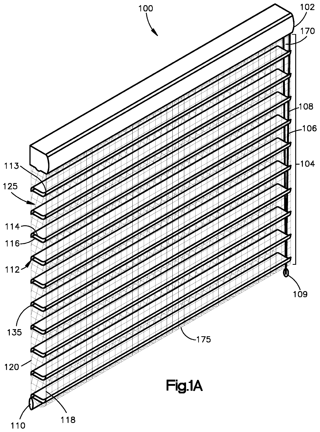
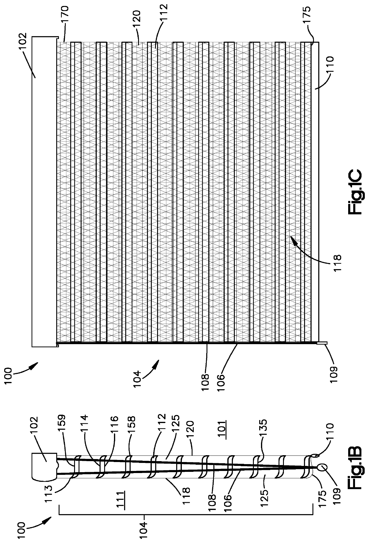
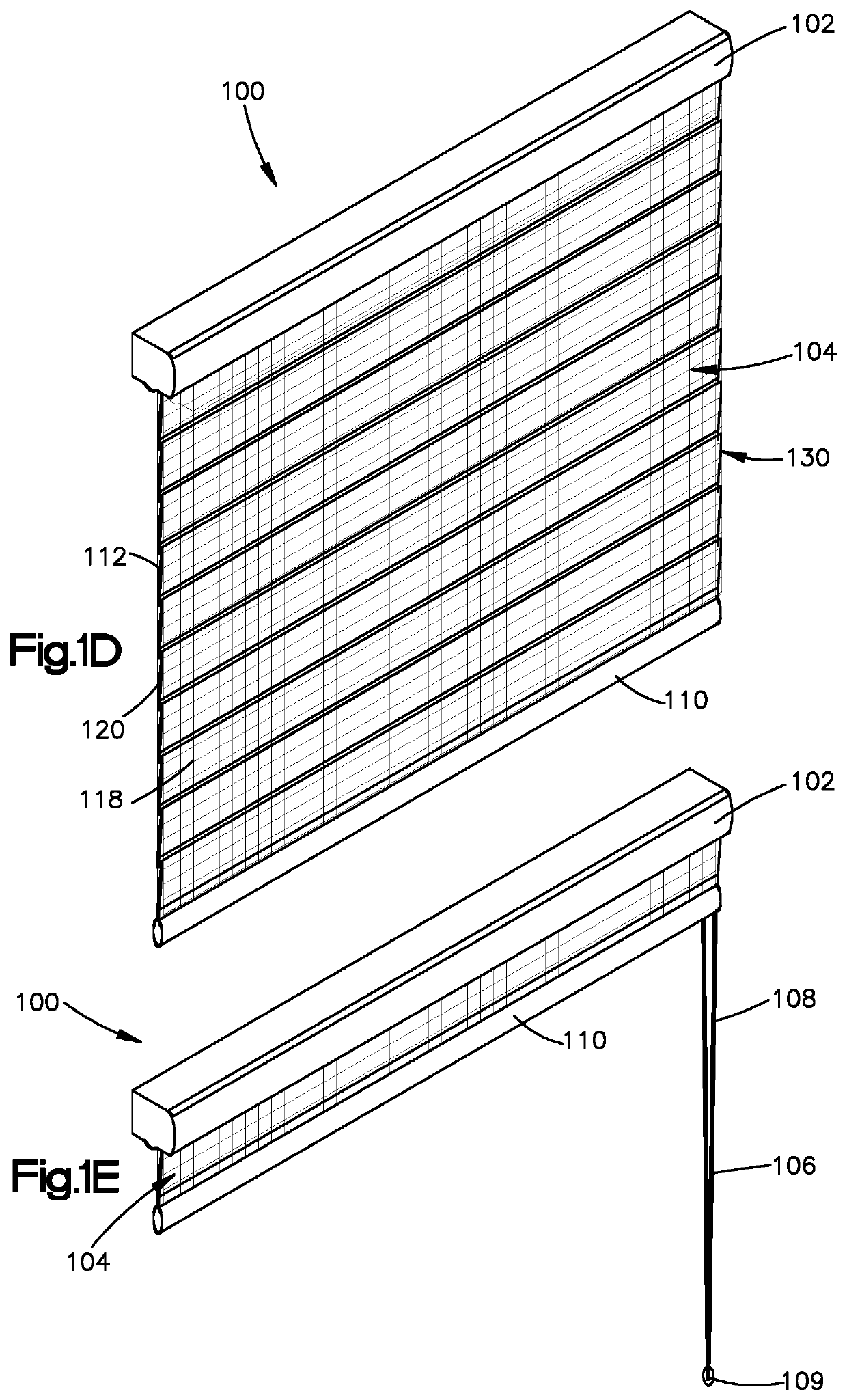
[0007]The present disclosure features a covering for architectural features, which may include windows, doorways, archways and the like, where the covering may have a panel formed of generally horizontal vane elements coupled to generally vertical support members which provides unique dimensionality, richness, and versatility. The covering or panel may be light-controlling and is aesthetically appealing as well as practical. The panel has a height and a width and generally includes a generally vertical front support element or member having a height and width, and a generally vertical rear support element or member having a height and a width, where the generally vertical rear support member is operably coupled to the front support member. Additional generally vertical support members may be included in embodiments. In one embodiment, the front and / or rear vertical support member may be substantially planar and flat, preferably with no folds or creases formed therein, and the rear vertical support member may be substantially parallel to the front vertical support member. The panel may further include a plurality of generally horizontal vane elements extending between, and which may be coupled, directly or indirectly, to the front and rear vertical support members, and in one embodiment both the front and rear vertical support members may control the movement and angular orientation of the vane elements, and may be laterally moveable with respect to each other. The plurality of moveable, generally horizontally extending vane elements may be manipulated and controlled by the vertical support members to control the amount of light inhibited, blocked, or transmitted by or through the panel.
[0010]In some embodiments, one or more of the vertical support members may be a dark color, for example, black, gray, or brown. In an embodiment, the rear vertical support member may be a darker color than the other sheers, including the front sheer, or vice versa. Having vertical support members with high openness factors and dark colors may increase view-through, and enhanced visibility of the vane elements may be achieved in certain embodiments. Having darker colors also might increase the strength and durability of the support members as the material forming the support members may be less susceptible to UV degradation.
[0013]In one embodiment the top and bottom layers or strips of material forming the multi-layered vane may be coupled, preferably continuously, along the entire length of their edges in regions to form apexes and coupled regions, where the coupled regions are preferably thin, of narrow width, and flexible, and may serve as a flex point or hinge which may permit the middle section of the top and bottom strips to separate more easily from each other to form a three-dimensional cellular vane. In one embodiment, the coupled regions are of narrow width and may have a width that is about the thickness of the layers or less, and preferably has a width as large as about 1.0 mm or less, more preferably between about 0.5 mm to about 0.1 mm, depending upon the thickness of the vane layers. In one embodiment, the material of the top and bottom layers are fused in the coupled regions, and the coupled regions may be formed by welding, including, for example, ultrasonic welding or hot-knife welding. Each of the top and the bottom layers of the vane may be thinner in an area immediately adjacent to the first coupled region than in other areas spaced farther from the coupled regions. In embodiments at least one of the coupled regions may be formed by one of the group consisting of fusing the top and bottom layers together, adhesively bonding the top and bottom layers together, sewing the top and bottom layers together, and combinations of fusing, adhesively bonding, and sewing the top and bottom layers together, or other means of attaching or coupling, such as staples, pins and tacks.
[0016]In another embodiment, by adjusting the relative length of the front and rear vertical support members, particularly the distance between the connection locations of the vanes to the front and rear vertical support members, vane closure for the covering and / or panel may be tightened and / or enhanced, particularly in a shading orientation, and the sequence of vane closure may be controlled.
[0017]The above embodiments of the panel may further include bottom rails, rollers, head rails, and control mechanisms to form a covering for an architectural feature. In embodiments, the covering may further include a bottom rail operatively associated with the bottom end of the panel, a movement mechanism to operate the roller, and / or a head rail to mount the roller. The covering in one embodiment may include a roller with the top end of the panel operatively associated with the roller. In yet another embodiment, a bottom rail may be associated with, preferably coupled to at least one of the rear vertical support member, the bottom-most vane, and / or the front vertical support member preferably along a single region or line of the bottom rail which may further assist with vane closure.

Problems solved by technology

The muted, milky view through is desirable for softening the light being transmitted through the covering, but in direct sun, full view through such sheer materials may be somewhat restricted.

Method used


Image

  • Covering for architectural features, related systems, and methods of manufacture
  • Covering for architectural features, related systems, and methods of manufacture
  • Covering for architectural features, related systems, and methods of manufacture

Examples


Embodiment Construction

[0045]In the following detailed description, numerous details are set forth in order to provide an understanding of an architectural covering, its method of operation, and method of manufacture. However, it will be understood by those skilled in the art that the different and numerous embodiments of the architectural covering, and its method of operation and manufacture may be practiced without these specific details, and the claims and invention should not be limited to the embodiments, subassemblies, or the specified features or details specifically described and shown herein. The description provided herein is directed to one of ordinary skill in the art and in circumstances, well-known methods, procedures, manufacturing techniques, components, and assemblies have not been described in detail so as not to obscure other aspects, or features of the architectural covering.

[0046]Accordingly, it will be readily understood that the components, aspects, features, elements, and subassemb...


PUM

PropertyMeasurementUnit
widthaaaaaaaaaa
widthaaaaaaaaaa
widthaaaaaaaaaa

Abstract

A covering for an architectural feature having generally horizontal vane elements coupled to and located between generally front and rear generally vertical support members, which in preferred embodiments are adjustable to control the amount of light transmitted through the covering. In one embodiment the covering has three dimensional multi-layered, cellular vanes, and in another embodiment, the one or more support members are formed of a dark color, and the rear support member(s) may be formed of material that is darker than the front support member(s), or vise versa. In another embodiment, the support members, e.g., sheers, have an openness factor, preferably as low as about sixty-five percent (65%) to as large as about ninety percent (90%). Other embodiments include structure, assemblies and methods for controlling the closure of the covering as well as embodiments of bottom rail assemblies. Also provided is a method of manufacturing the covering.

Description

CROSS-REFERENCE TO RELATED APPLICATIONS[0001]This application claims priority to U.S. Provisional Application No. 62 / 414,248, filed Oct. 28, 2016, and U.S. Provisional Application No. 62 / 525,549, filed Jun. 27, 2017, each of which is incorporated herein by reference in its entirety.FIELD OF THE DISCLOSURE[0002]The present disclosure relates to coverings for architectural features, which may include windows, doorways, archways and the like, and related systems, and methods of operation and manufacture. More particularly, the present disclosure relates to panels and / or coverings for architectural features having generally horizontal flexible vane elements coupled to one or more generally vertical support members, which provide light transmission and view-through controlling properties.BACKGROUND OF THE DISCLOSURE[0003]Current coverings for architectural features include sheer shadings sold under the brand name Silhouette® by Hunter Douglas, and as described in U.S. Pat. No. 5,313,999,...

Claims


Application Information

Patent Timeline
Patent Type & Authority Patents(United States)
IPC IPC(8): E06B9/264E06B9/266B29C65/74B29C65/08B29C65/00B29C65/18E06B9/262E06B9/34E06B9/382E06B9/386E06B9/24B29K67/00B29K105/00B29L31/00
CPCE06B9/264B29C65/086B29C65/18B29C65/743B29C65/7443B29C66/137B29C66/437B29C66/729B29C66/81417E06B9/262E06B9/266E06B9/34E06B9/382E06B9/386B29C66/71B29K2067/00B29K2105/256B29L2031/719E06B2009/2423E06B2009/2435E06B2009/2458E06B2009/2627E06B9/24D03D9/00D04B1/16
Inventor COLSON, WENDELL B.KUPERUS, KOEARL, BONNIERAHN, KELLYSMITH, KENT A.
Owner HUNTER DOUGLAS INC
Learn More