
Air vent having a control device

a control device and air vent technology, applied in the direction of air-treatment devices, vehicle heating/cooling devices, transportation and packaging, etc., can solve the problems of insufficient sealing of the air feed shaft, inability to transmit, rear vertical slats, etc., to improve the sealing of the closed position, reduce the gap, flexible and resilient

Active Publication Date: 2021-04-20
DR SCHNEIDER KUNSTWERKE
View PDF27 Cites 0 Cited by
  • Summary
  • Abstract
  • Description
  • Claims
  • Application Information

AI Technical Summary

Benefits of technology

The patent describes an air vent for motor vehicles that can be controlled to control the flow of air. The air vent includes slats that can be opened or closed to control the air flow. The slats are held in a spring-loaded position to compensate for any tolerances in the components. This ensures a better seal and prevents air leaks, resulting in improved air vent efficiency. A flexible and resilient sealing material can be used, such as plastic foams or rubber elements, to ensure the slats still move freely.

Problems solved by technology

However, the devices known from the prior art have the disadvantage that only an inadequate closure of the air feed shaft is possible by way of the rear vertical slats.
In particular, in the case of devices for control of an air flow with control elements arranged in the region of the slats it is not possible to transmit to the rear vertical slats by way of the control element a sufficient force to make a sealed closure possible.
In addition, the devices known from the prior art with substantially centrally arranged control elements have the disadvantage that these comprise a plurality of components which intrude into the flow channel of the air vent and thus produce an additional, but undesired, deflection of the air.
A sealed closure is therefore often not possible in the prior art, notwithstanding sealing means, since the components of the air vents have dimensional differences (tolerances) and in the case of repeated actuation the play of the components further increases.

Method used


Image

  • Air vent having a control device
  • Air vent having a control device
  • Air vent having a control device

Examples


first form of embodiment

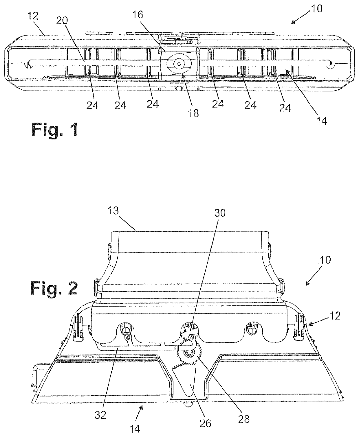
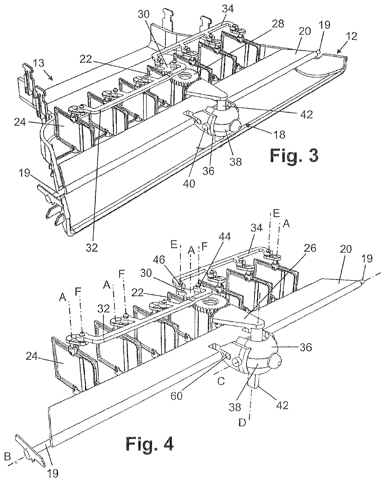
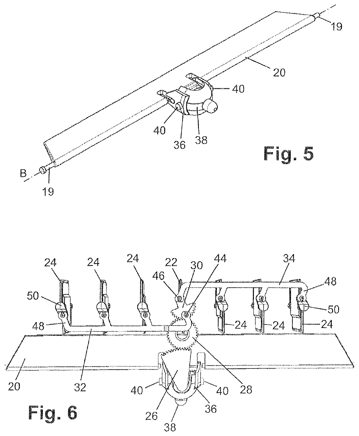
[0060]A first form of embodiment of an air vent 10 is shown in FIGS. 1 to 16 and described in the following with reference to FIGS. 1 to 16.

[0061]The air vent 10 comprises a housing 12. The housing 12 has at the front side thereof an opening which defines the air outlet region 14. A mounting web 16 is arranged in the air outlet region 14 and extends substantially centrally through the air outlet region 14. A control element 18 is arranged at the mounting web 16. The control element 18 serves the purpose of pivoting a substantially horizontally extending first control slat 20 and—by way of a first adjusting element 26, a first gearwheel 28 and a second adjusting element 30—second slats 24 so as to correspondingly deflect the air exiting by way of the air outlet region 14. In addition, the amount of air flowing out via the air outlet region 14 can be set by way of the control element 18, for which purpose the second slats 24 are moved into the closed position thereof.

[0062]The housing...

second form of embodiment

[0080]A second form of embodiment of an air vent 10 is shown in FIGS. 17 to 30 and described in the following with reference to FIGS. 17 to 30.

[0081]The air vent 10 of the second form of embodiment differs from the air vent 10 of the first form of embodiment in that no mounting web 16 is provided, but the second control part 78 serves as mounting. The second control part 78 is supported between an upper housing part and a lower housing part so that even in the case of increased control force applied to, for example, the first control part 76 no warping of the first control slat 20 occurs. The second control part 78 is mounted in the housing 12 to be rotatable about the second axis D so that analogously to the first described form of embodiment a turning or rotating of the second control part 78 causes swivelling or pivoting of the second slats 24 and the second control slat 22. If the first control part 76 is pivoted downwardly or upwardly, swivelling or pivoting of the first contro...


PUM


Abstract

An air vent has at least one first control lamella that is pivotably mounted in a housing, and a second lamellae extending orthogonally to the first control lamella. For controlling the amount and direction of outflowing air, an operating element is pivotable mounted about an axis that extends parallel to the pivot axis of the second lamellae, and which is coupled to a first adjustment element and to the first control lamella. The first adjustment element has a toothed segment, which is in engagement with a first gearwheel that is rotatably mounted on the housing. The first gearwheel is in engagement with a second adjustment element that is arranged on a second control lamella of the second lamellae, wherein the second control lamella is coupled with the other second lamellae by way of at least one connection rod, and the second gearwheel is of spring-mounted design.

Description

BACKGROUND OF THE INVENTION[0001]An air vent with a control device for controlling the direction and the amount of air flowing out of an air vent is described. In particular, an air vent with a control device constructed as a so-called one-knob control is described. The air vent has at least one control slat, which is pivotably mounted in a housing, and second slats extending orthogonally to the control slat and pivotably mounted in the housing, wherein the direction of the air flow exiting the housing is settable by way of the control slat and the second slats and in addition the amount of outflowing air is settable by way of the second slats.[0002]Various devices for controlling an air flow are known from the prior art, in which both the direction of the outflowing air and the amount of the outflowing air are settable by way of vertical slats arranged behind a control slat.[0003]DE 10 2013 100 534 A1 discloses a device for controlling an air flow, wherein a front horizontal slat c...

Claims


Application Information

Patent Timeline
Patent Type & Authority Patents(United States)
IPC IPC(8): B60H1/34
CPCB60H1/3421B60H2001/3478
Inventor GAREIS, JENNYHORNER, DOMINICSEEMANN, JUERGEN
Owner DR SCHNEIDER KUNSTWERKE
Learn More