Cable television apparatus improving high frequency characteristics

a high frequency characteristic and cable television technology, applied in the direction of television systems, coupling device connections, inductances, etc., can solve the problem that the dealer of the cable television system cannot extend the bandwidth to provide more services, and achieve the effect of improving the high frequency characteristics of the cable television apparatus

Active Publication Date: 2021-05-04
CABLE VISION ELECTRONICS
View PDF10 Cites 0 Cited by
  • Summary
  • Abstract
  • Description
  • Claims
  • Application Information

AI Technical Summary

Benefits of technology

[0016]The advantage of the present invention is to improve the high frequency characteristics of the cable television apparatus.
[0017]Please refer to the detailed descriptions and figures of the present invention mentioned below for further understanding the technology, method and effect of the present invention achieving the predetermined purposes. It believes that the purposes, characteristic and features of the present invention can be understood deeply and specifically. However, the figures are only for references and descriptions, but the present invention is not limited by the figures.

Problems solved by technology

However, the connection of the connector inside the cable television apparatus and the choke inside the cable television apparatus affects the high frequency characteristics of the cable television apparatus, so that the cable television system dealer cannot extend the bandwidth to provide more services.

Method used


Image

  • Cable television apparatus improving high frequency characteristics
  • Cable television apparatus improving high frequency characteristics
  • Cable television apparatus improving high frequency characteristics

Examples


second embodiment

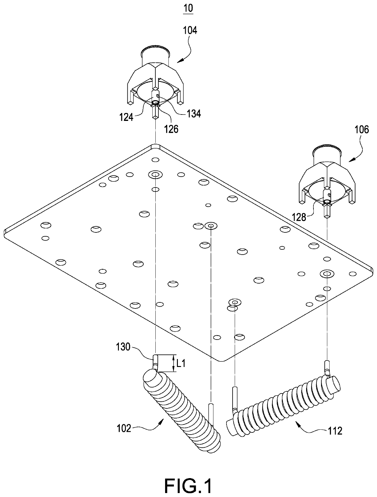
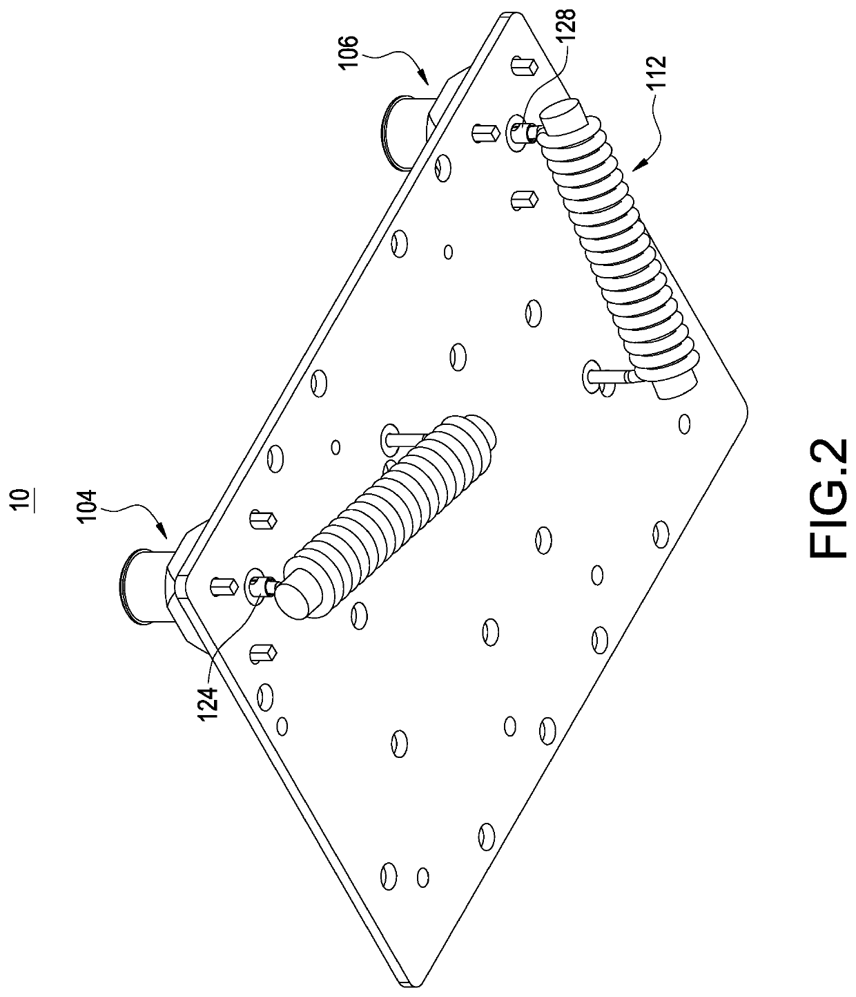
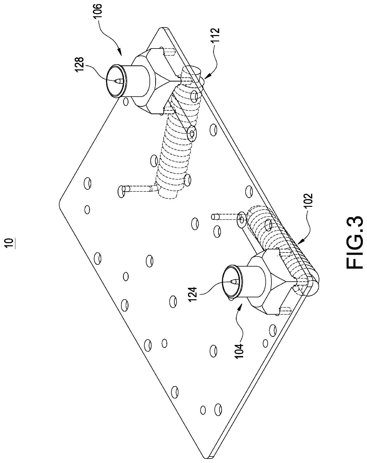
[0035]FIG. 6 shows a side perspective drawing of the cable television apparatus of the present invention. The descriptions of the elements shown in FIG. 6 which are the same as the elements shown in FIG. 1 to FIG. 5 and FIG. 9 to FIG. 10 are not repeated here for brevity. The first choke 102 is directly soldered to the first signal transmission unit 124. A length L1 of a pin 130 of the first choke 102 directly touched the first signal transmission unit 124 is less than 1 millimeter.

third embodiment

[0036]FIG. 7 shows a side perspective drawing of the cable television apparatus of the present invention. The descriptions of the elements shown in FIG. 7 which are the same as the elements shown in FIG. 1 to FIG. 6 and FIG. 9 to FIG. 10 are not repeated here for brevity. The first signal transmission unit 124 comprises a first signal transmission body 1241 and a second signal transmission body 1242. The second signal transmission body 1242 is electrically connected to the first signal transmission body 1241 and the first choke 102. The first signal transmission body 1241 and the second signal transmission body 1242 are connected perpendicularly. The second signal transmission body 1242 defines a soldering hole 126. A pin 130 of the first choke 102 inserts into the soldering hole 126 to be soldered to the second signal transmission body 1242.

fourth embodiment

[0037]FIG. 8 shows a side perspective drawing of the cable television apparatus of the present invention. The descriptions of the elements shown in FIG. 8 which are the same as the elements shown in FIG. 1 to FIG. 7 and FIG. 9 to FIG. 10 are not repeated here for brevity. A connection path length dl between the first signal transmission unit 124 and a pin 130 of the first choke 102 is less than 5 millimeters. A length L1 of the pin 130 of the first choke 102 is less than 1 millimeter. Although FIG. 8 does not show the second signal transmission unit 128 and the second choke 112, the second signal transmission unit 128 and the second choke 112 are similar with the first signal transmission unit 124 and the first choke 102, so that a connection path length between the second signal transmission unit 128 and the second choke 112 is less than 5 millimeters.

[0038]Because the second connector 106 is similar with the first connector 104, and because the second choke 112 is similar with the...


PUM


Abstract

A cable television apparatus improving high frequency characteristics includes a first connector and a first choke. The first connector is electrically connected to an input coaxial cable or an output coaxial cable. The first choke is electrically connected to the first connector. The first connector includes a first signal transmission unit. The first choke is used to block a cable television signal. The first choke allows a first current flowing through the first choke. The first current is greater than or equal to 10 amperes. The first choke is directly touched the first signal transmission unit, or a connection path length between the first signal transmission unit and a pin of the first choke is less than 5 millimeters.

Description

BACKGROUND OF THE INVENTIONField of the Invention[0001]The present invention relates to a cable television apparatus, and especially relates to a cable television apparatus improving high frequency characteristics.Description of the Related Art[0002]Currently, the cable television system is very popular. The cable television system transmits television programs and network signals to client sides through coaxial cables.[0003]However, the connection of the connector inside the cable television apparatus and the choke inside the cable television apparatus affects the high frequency characteristics of the cable television apparatus, so that the cable television system dealer cannot extend the bandwidth to provide more services. Currently, the cable television system dealer needs more simple method for improving the high frequency characteristics to increase the available bandwidth to provide more services.SUMMARY OF THE INVENTION[0004]In order to solve the above-mentioned problems, an ...

Claims


Application Information

Patent Timeline
Patent Type & Authority Patents(United States)
IPC IPC(8): H04N7/10H03H7/01H01R24/50H04N5/38H01R103/00
CPCH03H7/0123H01R24/50H03H7/0138H04N5/38H04N7/102H01R2103/00H01F17/045H01F27/292H01F2027/297H03H7/46
Inventor LEE, CHIEN-CHUNGTING, I-SHENG
Owner CABLE VISION ELECTRONICS
Why Eureka
Try Eureka